
WINDOWS
WINDOWS
WINDOWS
This PDF was last updated on 09/08/2026. Please redownload if you’re currently working from an older version.
WHEN TO USE THIS BASIS OF DESIGN SECTION
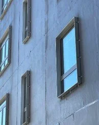
This BOD section should be used for both new construction projects and window replacement at existing buildings. It is understood that some criteria may not be applicable in all replacement scenarios. Alternate requirements applicable to window replacement are noted in this BOD. The objective is to guide the design and installation of windows that will offer a high level of performance – this relates to performance of the window unit itself as well as integration of the window in the water and air control function of the exterior wall.
The right windows can bring benefits to resident comfort, condensation resistance, noise control, and reduced heating and cooling loads. Achieving these benefits depends on appropriate window specification as well as on proper installation details. Proper installation of windows is also critical to protecting the durability as well as the maintainability of POAH properties. This BOD provides requirements for specifications for POAH projects by climate zone. This BOD also provides guidance on installation details to ensure robust performance is achieved. The requirements listed and guidance provided in this BOD section are intended to serve as minimum standards. Projects may exceed these requirements as circumstances allow.
Window Replacement in Designated Historic Buildings:
For projects using historic tax credits, all window details will have to be reviewed by local and federal governing authorities. It is also important that window installation, configuration, and details do not elevate risk of durability and comfort problems. Where historic restrictions prevent the use of specifications and installation details outlined in this BOD, projects shall submit window specifications and details to Building Design and Performance for review.
WINDOW PERFORMANCE REQUIREMENTS
Window product ratings are based on three primary performance parameters (as indicated on the NFRC label, see below):
U-factor, relates to the amount of heat that is conducted through the window. A lower U-factor is better because less heat is conducted out through the window in cold weather and less heat is conducted through the window into the space in hot weather. A window with lower u-factor tends to feel less “drafty” for people sitting near the window.
Solar Heat Gain Coefficient (SHGC), a measure of how much of the sun’s radiant heat is transmitted through the glass. Generally, the warmer the climate, the lower the SHGC should be. In climates with significant heating load, higher SHGC for south-facing windows can be beneficial in certain circumstances. SHGC should be reported for the window unit as a whole, that is, accounting for the radiant transfer through the glass as well as the lack of radiant heat transfer through the frame. SHGC can also be reported for the center of glass – in which case it relates just to the property of the glass used.
Visible Light Transmittance (VT), is the percentage of visible light transmitted through the glass. Higher is generally better. As with SHGC, VT is typically reported for the whole window and can also be reported for just the glass used in the window. It is important that the VT number is not too low because a low visible light transmittance can make a space feel dark and gloomy even with large areas of window. The visible transmission through the glass itself tends to be the parameter that most impacts how the light through a window feels. Perception of visible transmittance and light quality is somewhat subjective. It is good practice to obtain samples of the glass options before making a final selection.
Two other voluntary criteria (not always included in NFRC label) are also important to window performance:
Air leakage, this should be below 0.1 cfm/sf at 50 Pascals.
Condensation Resistance Factor (CRF), in cold climates, should be 75 or higher.
The Window Criteria table below lists requirements for all climate zones. The next table highlights parameters in each climate zone where POAH has properties.
REQUIRED CRITERIA ACROSS ALL CLIMATE ZONES
REQUIRED CRITERIA ACROSS ALL CLIMATE ZONES
REQUIRED CRITERIA ACROSS ALL CLIMATE ZONES
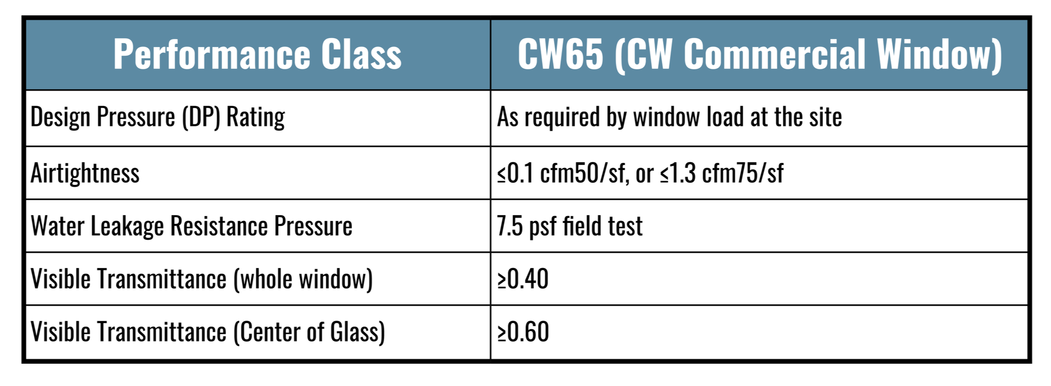
Performance Requirements:
Windows must comply with local energy code. The more stringent requirements between ENERGY STAR, the local energy code, and the table below must be followed.
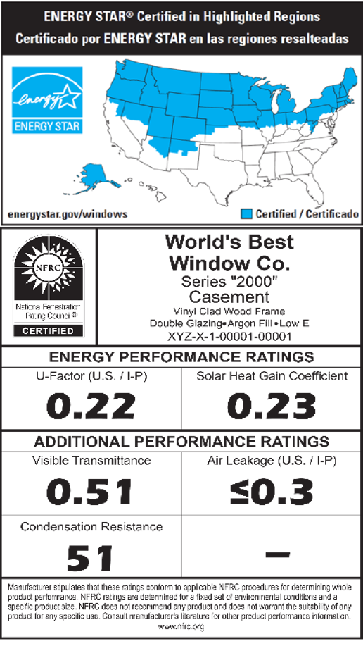
The National Fenestration Rating Council (NFRC) label is needed for verification of energy code compliance. The NFRC label (typically found on glazing) displays whole-window energy properties and appears on all fenestration products which are part of the ENERGY STAR program (www.nfrc.org).
Proper window installation is necessary for optimal performance, to avoid air and water leakage. Always follow manufacturers’ installation guidelines and use trained professionals for window and skylight installation.
Windows must be ENERGY STAR certified. Often energy star certified windows meet or exceed energy code requirements. Follow this link to determine the minimum U-Factor and Solar Heat Gain Coefficient (SHGC) for your area.
Window performance can also be based on location and climate zone. The more stringent requirements between ENERGY STAR and the local energy code must be followed.
REQUIRED CRITERIA BASED ON CLIMATE ZONE
REQUIRED CRITERIA BASED ON CLIMATE ZONE
REQUIRED CRITERIA BASED ON CLIMATE ZONE
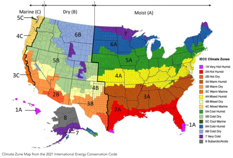
The table below represents window performance criteria required for POAH new construction and window replacement projects. Some performance requirements are dependent on climate zone of the building’s location. See the map below for identification of climate zone.
Link to Window Bid Tab: for use in new or replacement windows. Architect should confirm code compliance metrics, and GC should complete the bid tab with window performance specs for each window bid for the project. POAH uses this tab to evaluate performance against cost.
Clicking this link will automatically start a download of the bid tab Excel file. Use this bid tab for comparison of window/window manufacturers. Columns C - G are editable. Please complete and submit to owner for review and approval.
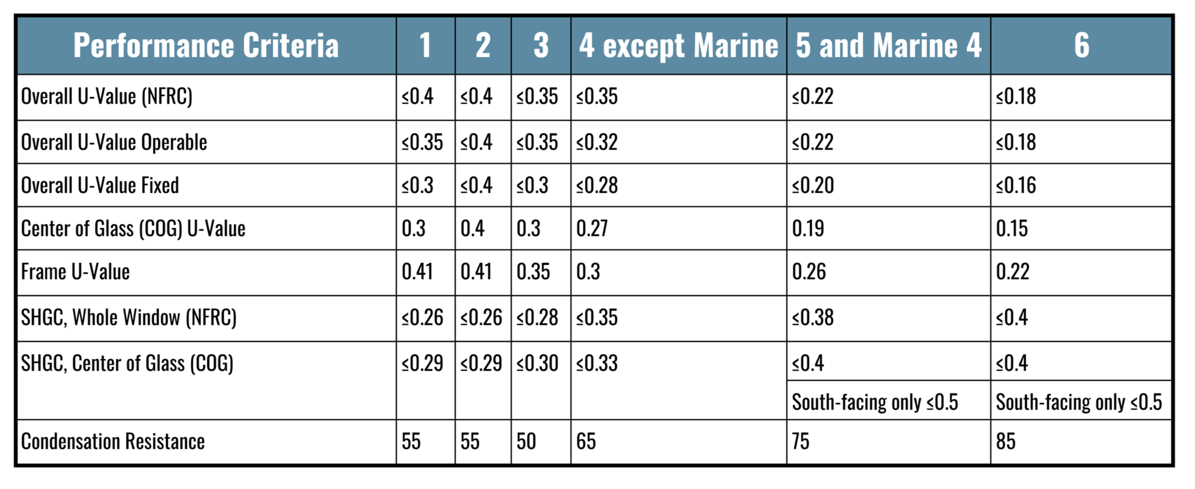
Columns 1-6 indicate climate zones, as shown in the map below
SAFETY REQUIREMENTS
Opening Limiters: POAH and POAH Communities window limiter policy: windows should be limited to opening 4” maximum.
Impact Glazing: In high wind locations, local jurisdictions and/or prudent design will require large-missile rated windows in accordance with ASTM E1996. Architect to specify locations
Tempered Glazing: Architect to specify locations. Where required by local building code install per code. If not required by local building code, provide tempered glazing:
In all doors (swinging and sliding)
At door sidelights
Glazing within 24” of the finished floor
In stairways where glazing is within 48” of landing or stair tread
Sill Height: POAH prefers the sill height to be no less than 24 inches in all locations in New construction (residential and common area). In rehab projects that also involve a new cladding system, window replacement should be leveraged as an opportunity to adjust the sill height of the window. Historic buildings will need to match the size of the existing opening.
Frame Material: windows are manufactured with a range of frame materials including fiberglass, wood, un-plasticized PVC (UPVC), aluminum, and vinyl (PVC).
POAH’s preferred window frame materials are, in order:
Fiberglass
uPVC
Thermally broken aluminum
Regular, plasticized, vinyl windows are to be avoided due to chemical toxicity concerns that are not adequately addressed by manufacturers in today’s window marketplace.
ACCEPTABLE WINDOW OPERATION
Window operation is a key decision to ensure high performance. Acceptable operation includes awning, fixed (in combination with operable), and casement (inswing or outswing). If a window has a tilt-turn function, the tilt function must be deactivated.
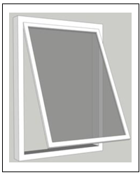
Awning
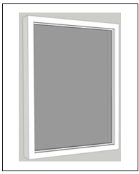
Fixed
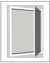
Casement
Window operation (historic buildings): Window replacement at buildings designated historic or in projects employing historic tax credits may have restrictions on the type (operation) of window, the frame material, and certain panning details. Where replacement windows must replicate double-hung windows, investigate the use of simulated double hung windows. Several manufacturers provide windows for historic and landmarks projects that maintain the appearance of a double hung window with a fixed sash over a casement sash that is set back from the upper sash to create the appropriate shadow line of a meeting rail. If double hung is the only option, the upper sash should be fixed and sealed to be air-tight.
REQUIRED DESIGN + CONSTRUCTION DETAILS
REQUIRED DESIGN + CONSTRUCTION DETAILS
REQUIRED DESIGN + CONSTRUCTION DETAILS
DESIGN DETAILS
The window details must clearly demonstrate the water control for the window opening (flashing and drainage) as well as the air control function and how that is connected from the wall, into the rough opening, and to the window.
SEE EXAMPLE DETAILS BELOW.
Details must show a two-stage joint configuration between the window and the rough opening (R.O.)
with a full perimeter air seal at the inside perimeter of the window frame, and
include shielded weeps that drain to the exterior of the drainage plane at the sill.
Barrier sealed (i.e. without provision for drainage) installations are not acceptable.
The sill of the rough opening must be configured to support the window flashing and direct water to the exterior
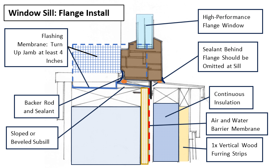
The sill of the window opening must provide a sloped substrate for the flashing membrane. Slope is toward the exterior with a drop >= ¼”
Windows must be sized to accommodate a sloped sill. Typically, the slope is achieved by installing a piece of beveled siding or similar material over the sill framing. This can be expected to subtract ~1/2” from the gross rough opening height.
A back dam may be used in combination with a sloped sill substrate, however, back dams at window openings create challenges that the design and installation team will need to resolve, namely 1) a back dam restricts access for manipulation of shims, and 2) when used with sheet membrane flashing, a back dam creates additional bends and folds in the membrane.
For each unique window type or wall assembly provide details for the head, sill, and jamb conditions.
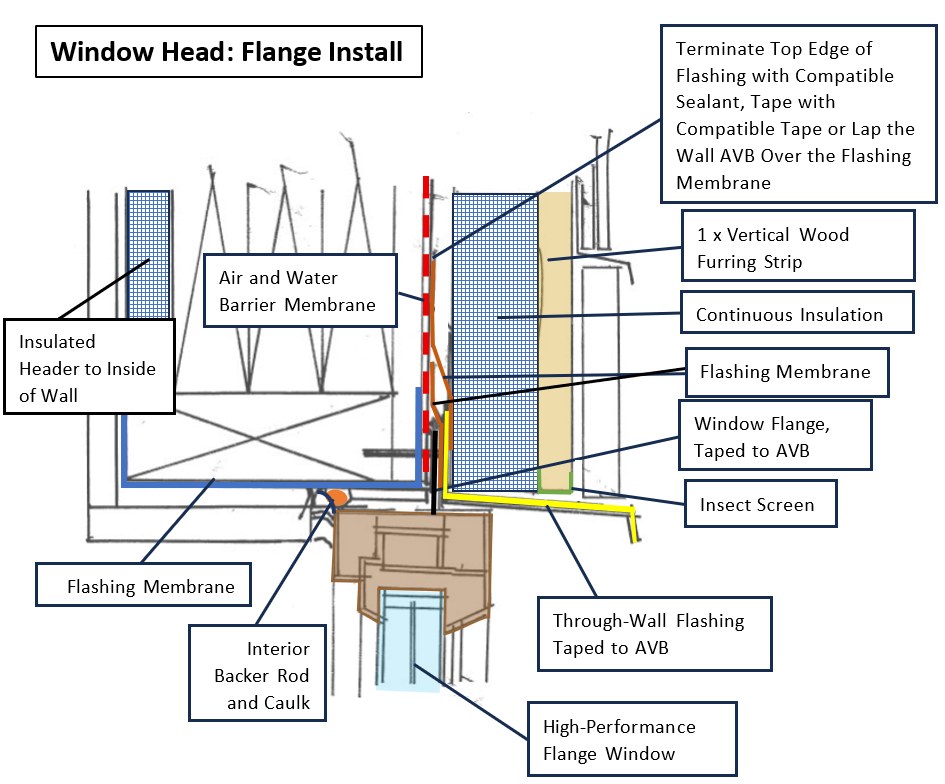
Head Details: provide an adhered membrane flashing wrapping into the opening beyond the extent of the window frame. The top, upward-facing edge of flashing must be terminated with a tape or compatible sealant, OR the air and water barrier of the wall must lap over the head flashing.
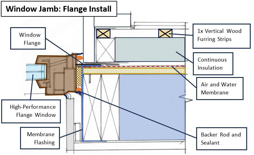
Jamb Details: provide an adhered membrane flashing wrapping into the opening beyond the extent of the window frame.
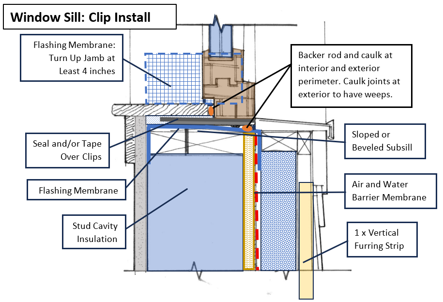
Sill Details: provide a positive slope to the exterior at the sill of the rough opening. Provide an adhered membrane flashing wrapping into the opening beyond the extent of the window frame. The outside edge of the sill flashing membrane must lap over the air and water barrier of the wall. See example details below.
SILL FLASHING INSTALLATION
Flashing at the sill for the rough opening shall be installed as follows:
A flexible stretchable membrane flashing OR a fluid-applied flashing membrane shall be placed at the sill-to-jamb corners prior to placement of straight flashing membrane at the sill and jambs.
Sill flashing membrane is to lap min. 4” up the jamb so that Jamb flashing membrane can lap onto the up-turned sill flashing membrane above the sill, provide min. 2” lap.
Membrane end laps are to be avoided along the sill of the rough opening.
The photos below demonstrate the sequence for flashing a window rough opening.
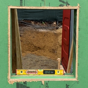
Figure 1: Framed window rough opening with back dam
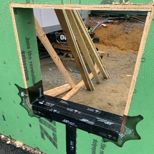
Figure 2: Sill corners flashed with flexible membrane. Sill flashing membrane turned up jambs minimum 4”.
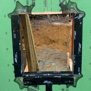
Figure 3: Jambs flashed overlapping flashing at sill corners. Head corners flashed.
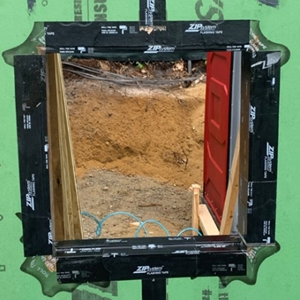
Figure 4: Head flashing extends to interior and laps over air barrier at exterior.
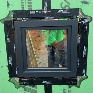
Figure 5: Window installed in fully flashed rough opening.
QUALITY CONTROL REQUIREMENTS
WINDOW MOCK-UP
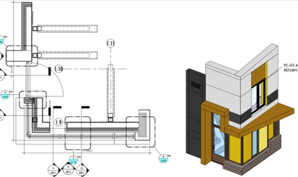
All window projects shall involve a mock-up installation where POAH and/or POAH’s consultants have an opportunity to review:
The installation of flashing membranes (and the order of flashing membranes) in the window opening.
Integration of window opening flashing with the air and water barriers of the wall system.
Installation of the window in the opening.
Sealing of the interior perimeter of the window.
For new construction projects POAH prefers a free-standing mock-up. For retrofit projects the mock-up should use an existing window opening representative of a typical window condition.
MOCK-UP TESTING
Mock-up window installations as well as early post-mock-up window installations shall be tested for air leakage performance (e.g. ASTM E783) and water leakage performance (e.g. ASTM E1105).
POAH does not accept a 2/3 reduction, relative to lab testing, for field testing pressure.
The mockup window installations shall be tested to the specified/required test pressure. If the mock-up installation passes the water leakage test criteria, it shall be tested repeatedly at incrementally higher pressures and as high as 12 psf (or as acceptable to window manufacturer). This will allow for identification of weaknesses that may emerge in subsequent installations.
Details for window installation shall be revised according to lessons from the mock-up installation and testing.
Window installation beyond the mock-up shall not proceed until issues with the mock-up installation are resolved to POAH’s satisfaction.
TESTING (IN BUILDING)
Window installations after the mock-up installation shall be tested for air and water leakage performance at the following rate:
The first installation of each unique window type shall be tested
If the project involves two (2) or fewer unique window types, then no fewer than two (2) initial window installations after the mock-up shall be tested.
If the initial window installations meet requirements in both the air leakage and water leakage testing, then remaining windows shall be tested at a 5% sampling rate.
If any of the initial window installations (after the mock-up installation) fail to meet the requirements in testing, then the window shall be repaired and re-tested. Additionally, another window of the same type shall be tested.
For each instance of a window installation failing to meet the performance requirements in the field test, the window shall be repaired and retested and another window of the same or similar type shall be tested.
EXAMPLE DETAILS
CLIP WINDOW INSTALLATION DETAILS
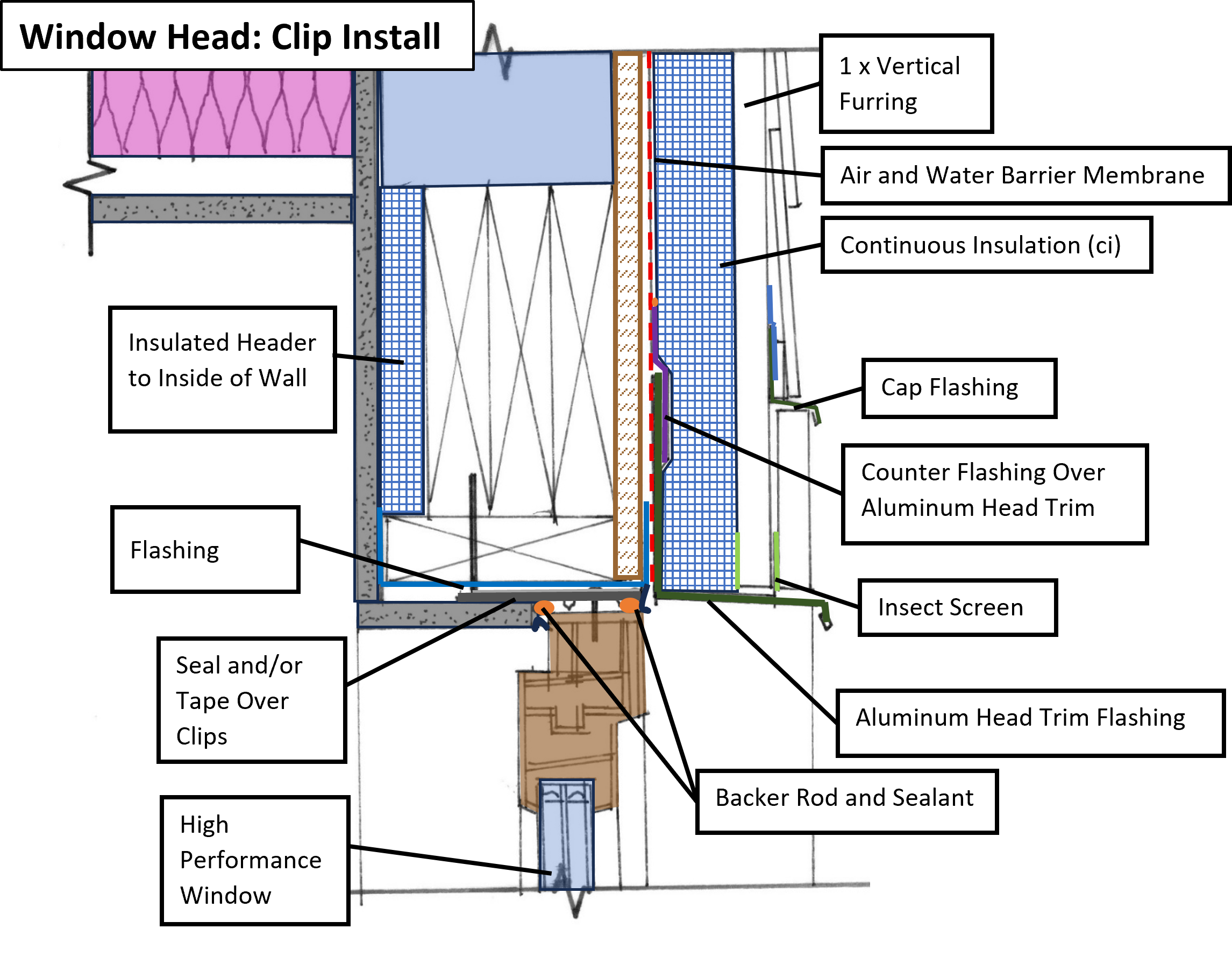
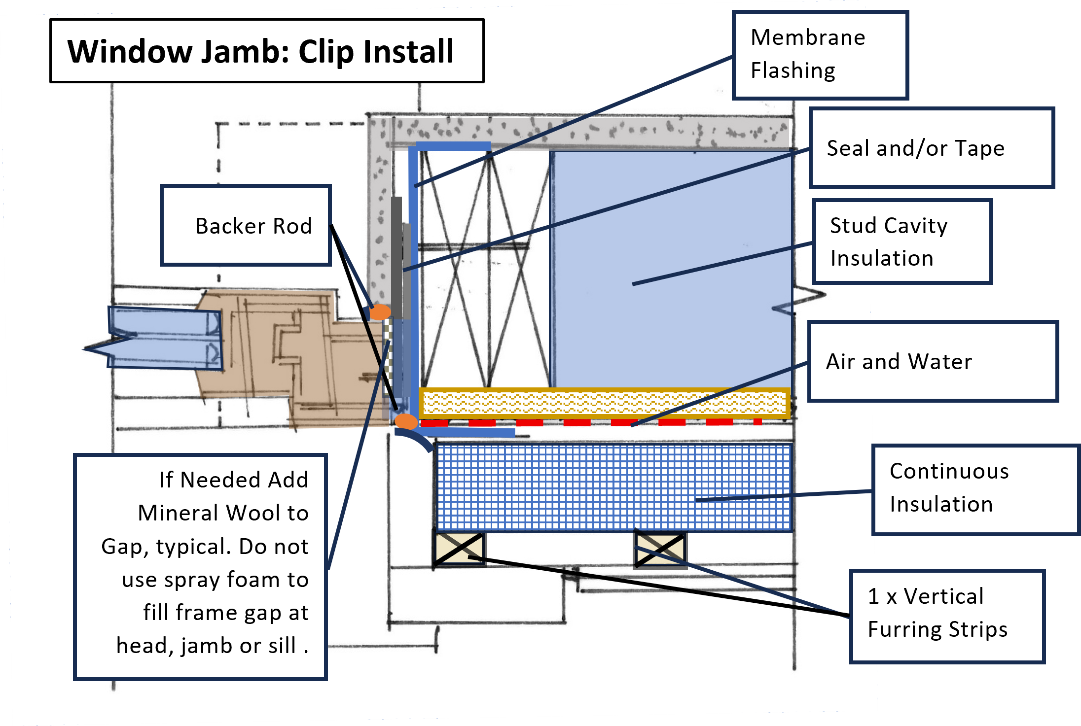
Special considerations for a clip or anchor strap (non-flanged) window installation. See details below.
After the window is fully fastened, apply tape over each clip sealing it to the flashing membrane. This helps prevent leakage through small gaps around the clips. Alternatively, or in addition to, the clips can be fully embedded in sealant.
Proceed with backer rod and sealant at interior and exterior perimeter of window. Leave two equally spaced weep holes in sealant at the exterior sill. Weep holes are to be ¼ inch in width and located at least three inches away from the jambs.
FLANGE WINDOW INSTALLATION DETAILS
Special considerations for a flanged window installation. See details below.
Ensure window is detailed so that the flange can be properly fastened to structure (if RO is too big, fasteners can miss framing). If Zip-R is used, need longer screws.
Check with Manufacturer if flange is integral. Flange may need to be sealed to window frame if not one piece.
TERMS & VOCABULARY
TERMS & VOCABULARY
TERMS & VOCABULARY:
Copyright © 2016, Efficient Windows Collaborative.

Copyright © 2016, Efficient Windows Collaborative
U-Factor
The rate of heat loss is indicated in terms of the U-factor (U-value). This rate of non-solar heat loss or gain through a whole window assembly is measured in Btu/hr-sf-°F. The lower the U-factor, the greater a window’s resistance to heat flow and the better its insulating value.

Copyright © 2016, Efficient Windows Collaborative
Solar Heat Gain Coefficient (SHGC)
The SHGC is the fraction of incident solar radiation admitted through a window. SHGC is expressed as a number between 0 and 1. The lower a window’s solar heat gain coefficient, the less solar heat it transmits. Whether a higher or lower SHGC is desirable depends on the climate, orientation, shading conditions, and other factors.

Copyright © 2016, Efficient Windows Collaborative
Visible Transmittance (VT)
The VT is an optical property that indicates the amount of visible light transmitted. VT is a whole window rating and includes the impact of the frame which does not transmit any visible light. While VT theoretically varies between 0 and 1, most values are between 0.3 and 0.7. The higher the VT, the more light is transmitted.

Copyright © 2016, Efficient Windows Collaborative
Air Leakage (AL)
AL is expressed in cubic feet of air passing through a square foot of window area (cfm/sf). The lower the AL, the less air will pass through cracks in the assembly. AL is very important, but not as important as U-factor and SHGC.

Copyright © 2016, Efficient Windows Collaborative
Condensation Resistance (CR)
CR measures how well a window resists the formation of condensation on the inside surface. CR is expressed as a number between 1 and 100. The higher the number, the better a product is able to resist condensation. CR is meant to compare products and their potential for condensation formation. CR is an optional rating on the NFRC label.