ROOFING
ROOFING
ROOFING
This PDF was last updated on 04/11/2024. Please redownload if you’re currently working from an older version.
GENERAL INFORMATION
GENERAL INFORMATION
WHEN TO USE THIS BASIS OF DESIGN SECTION:
This BOD section should be used for both new construction projects and re-roofing of existing buildings. The objective is to guide the design and installation of roofing systems that will offer a high level of performance. See the Building Enclosure section for performance requirements of roofs related to compartmentalization and insulation. Roofing systems that perform well will protect building durability as well as the maintainability of POAH properties. The requirements listed in this BOD section are intended to serve as minimum standards. Projects may exceed these requirements as circumstances allow.
REQUIREMENTS
REQUIREMENTS
REQUIREMENTS:
ROOF STRUCTURE:
All new roofs need to be engineered to support a future PV or Solar Thermal system.
ROOF PENETRATIONS:
All new roof design and construction projects must coordinate with plumbing and mechanical design/trades to locate vents on the north slope such that roof surfaces facing south or within 90 degrees of south are maintained clear of obstructions.
All re-roofing projects must thoroughly pursue moving plumbing vents and other obstructions as part of the re-roofing project. Project managers should consult with POAH Design + Building Performance for cases where moving the penetrations is not immediately feasible.
REQUIRED DETAILS:
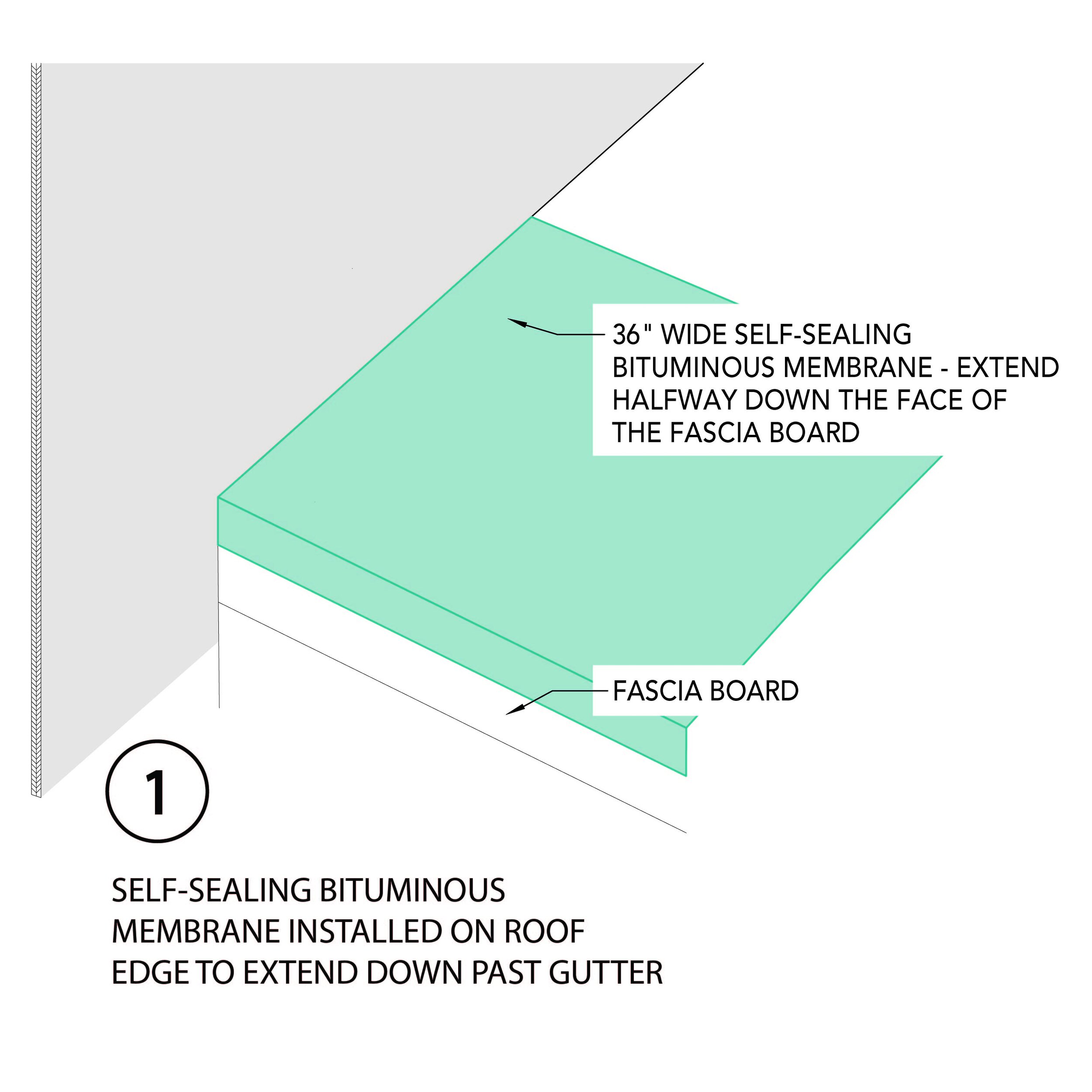
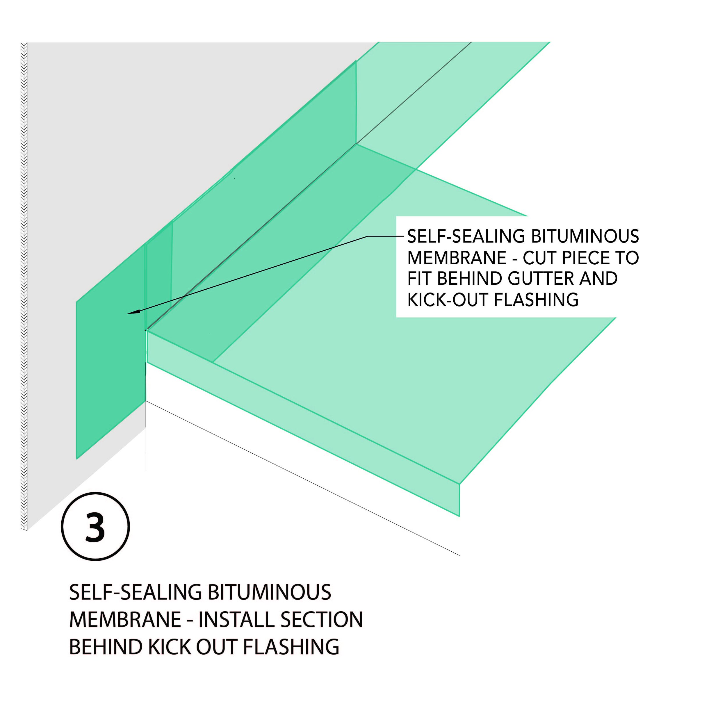
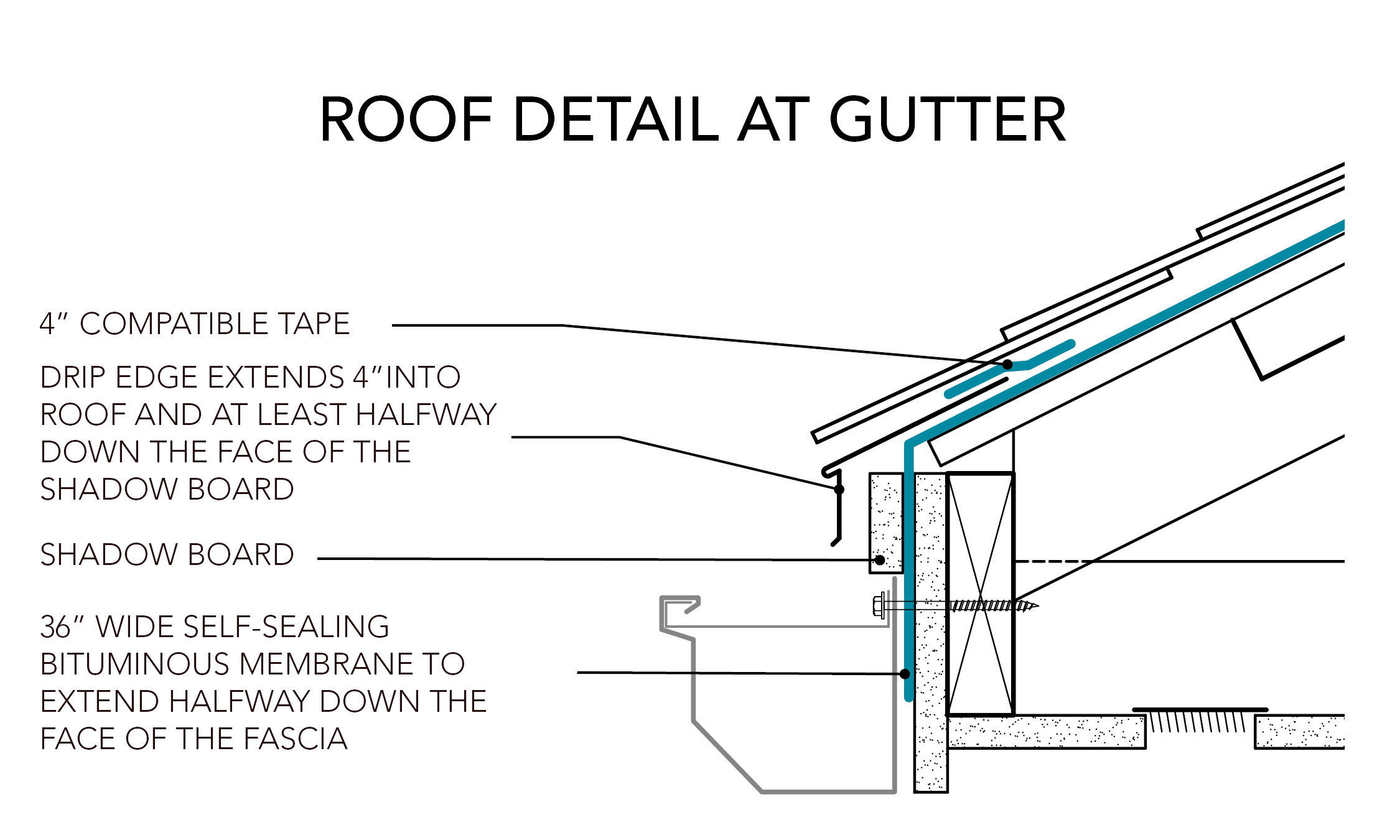
Roof edge membrane: Install a self-sealing bituminous membrane or the equivalent at the roof edge prior to the drip edge. Install the membrane to extend halfway down the face of the fascia (see detail below).
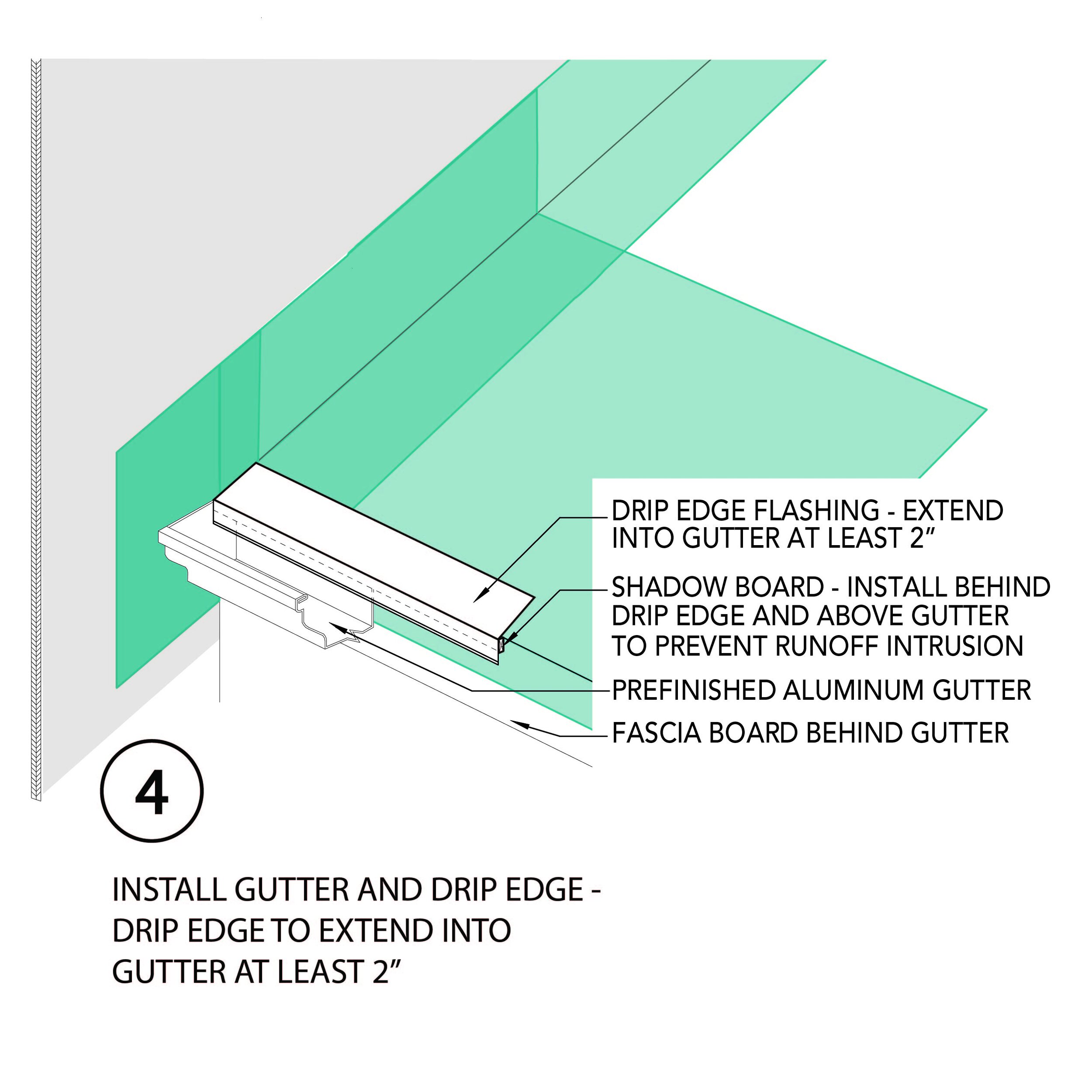
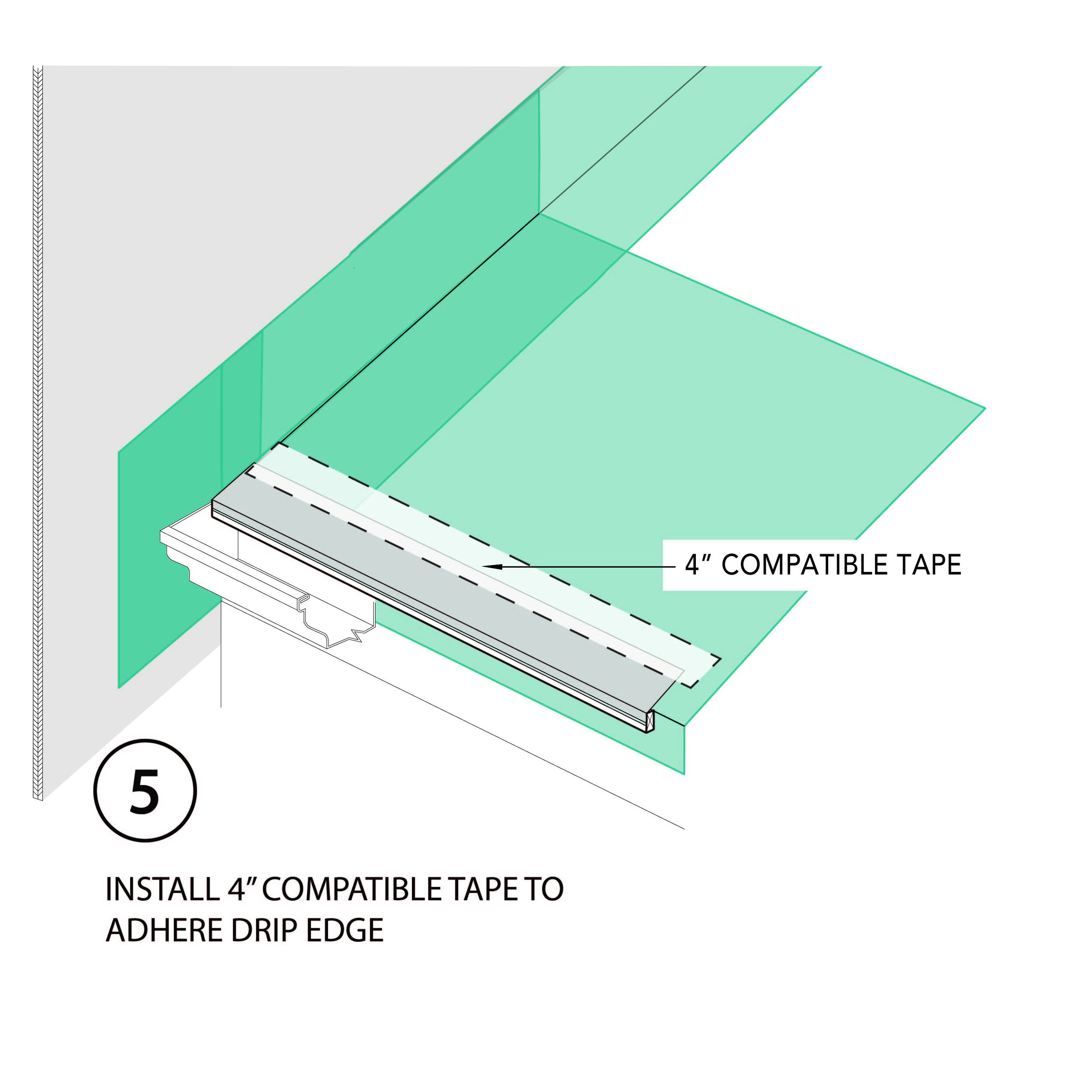
Drip edge: A metal drip edge shall be provided along the entire roof perimeter. The metal drip edge should have a drip leg that extends at least 1” below the sheathing, ½” from adjacent fascia or rake trim and at least 2” into the gutter. Install a shadow board per the detail below to ensure the rain is directed into the gutter. The top edge of the drip edge shall be covered with a minimum 12” self-sealing bituminous membrane or the equivalent.
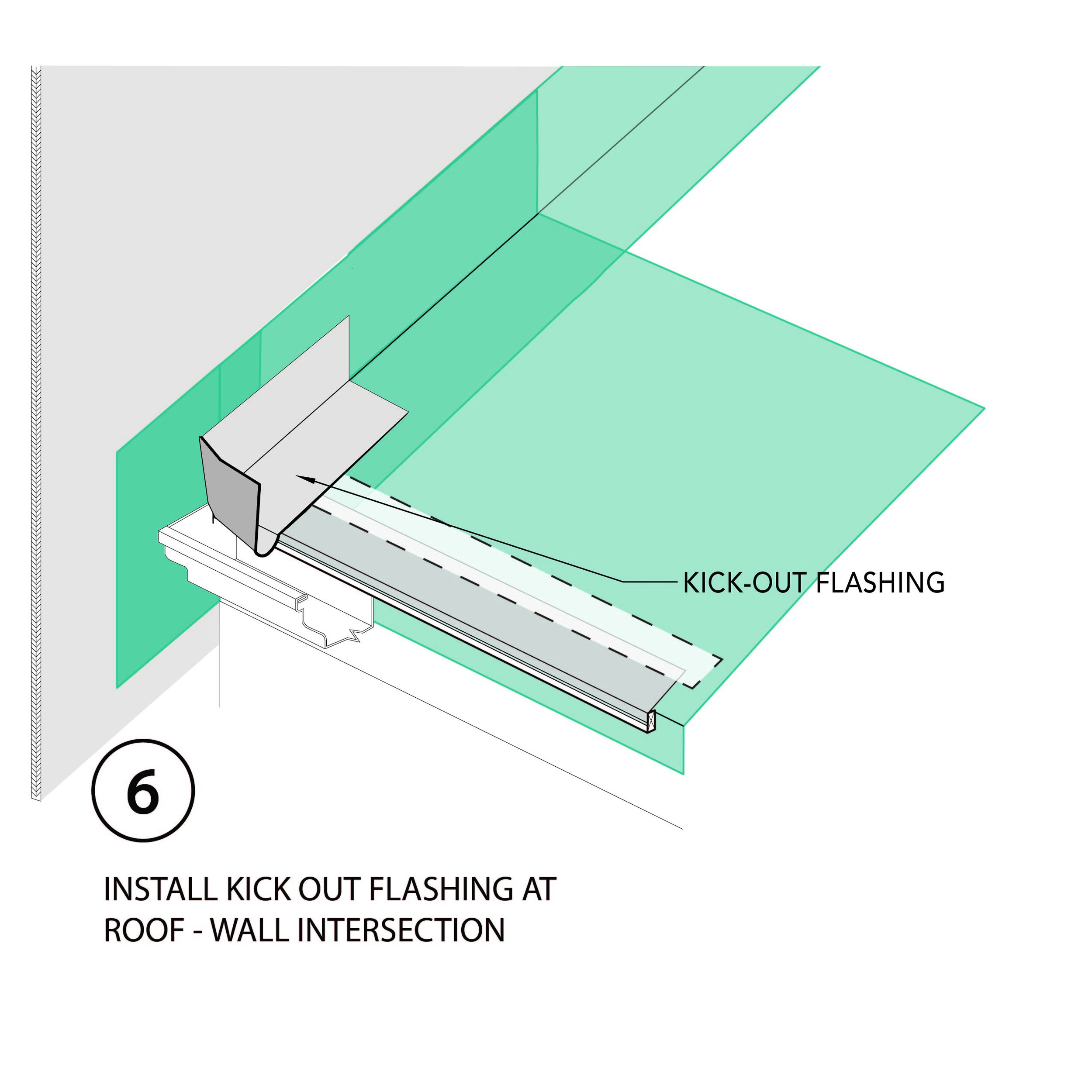
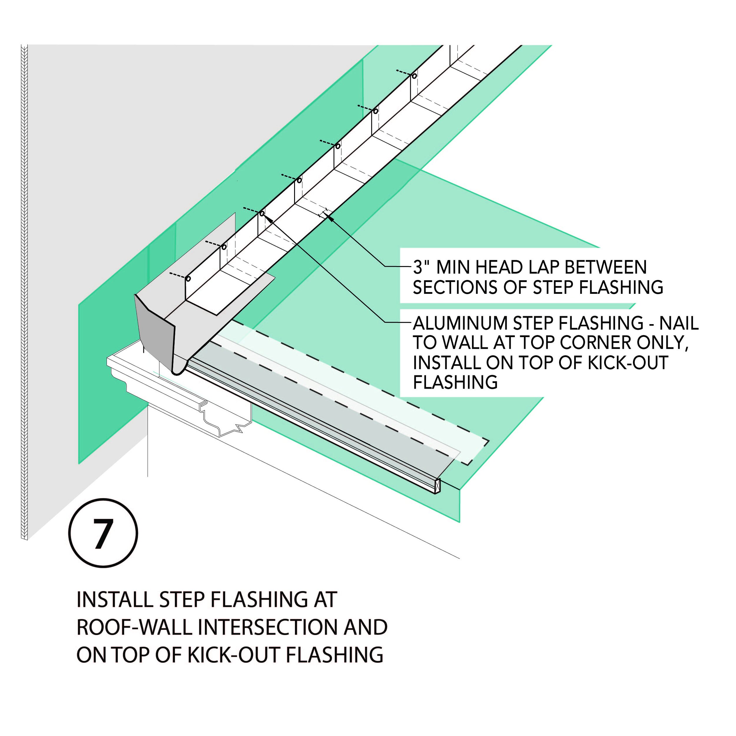
Kick-out flashing: Install an aluminum flashing (kick-out) to divert water away from where a sloped roof edge intersects a vertical sidewall. The vertical leg of the kick-out flashing shall extend at least 4” on the wall surface above the roof deck and shall be integrated with the drainage plane of the wall. The kick-out flashing is required regardless of the type of wall cladding. A kick-out/diverter flashing should also be installed at the end of eaves where a gutter is installed at the eave and the gutter does not extend past the end of the eave. See the sequence diagram below for proper installation.
Ice and Water barrier: In locations that experience snow fall, a self-sealing bituminous membrane, or the equivalent shall be installed at the roof edge and extend from the edge of the roof deck to a point not less than 24 inches to the inside of the exterior wall line of the building. See image below.

Roof plan showing ice and water barrier locations
Roof-to-wall intersections:
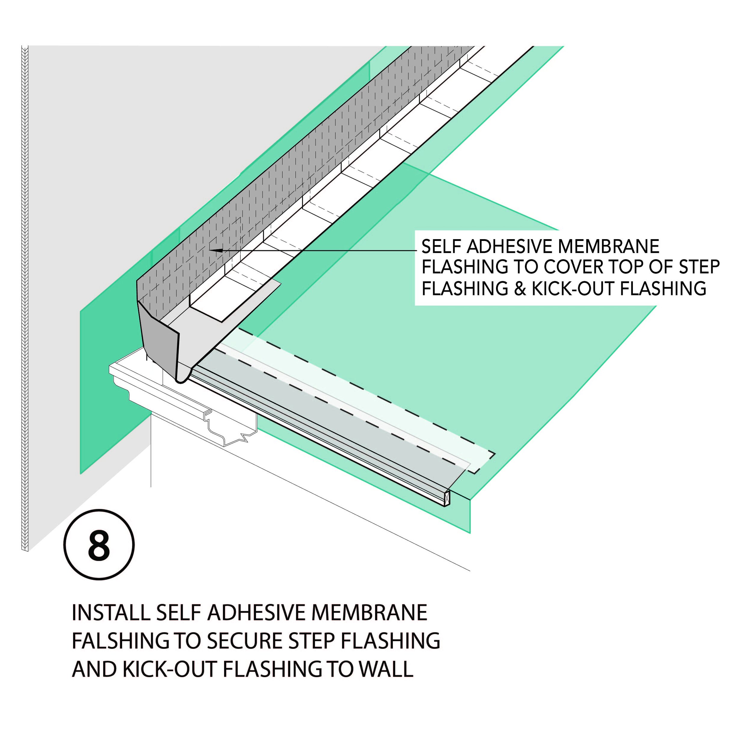
Shingled roofs: Step flashing shall be installed at wall and roof intersections. A self-sealing bituminous membrane or the equivalent shall be installed at roof-wall intersections behind step flashing and extending at least 12” up the vertical face of the wall sheathing. The top edge of this adhered water control membrane shall be taped to the sheathing with compatible tape. See detail below.
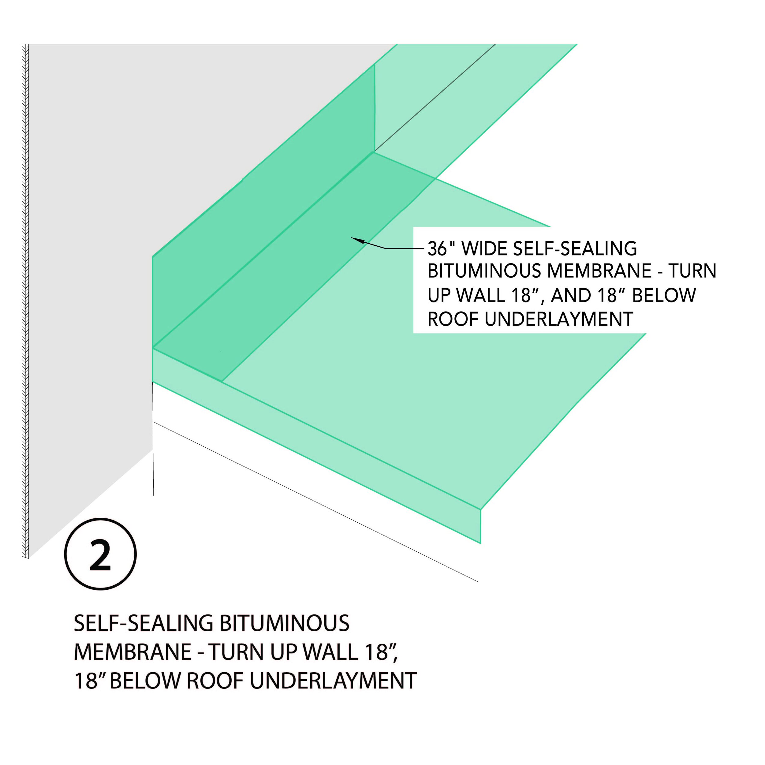
Metal and Membrane roofs: Install a continuous flashing (with separate pieces lapped shingle fashion), between the roof and wall sheathing. The continuous flashing shall be self-sealing bituminous membrane or the equivalent at least 36” wide. It shall be installed to extend at least 18” onto the roof sheathing and 18” onto the wall sheathing.
Roof Valleys and Changes in Slope: Install a self-sealing bituminous membrane or the equivalent at all valleys and all changes is roof slope. Note that this water protection membrane must not obstruct intentional roof vent openings.

Self-sealing bituminous membrane installed at roof valley
Roof Penetrations: Fully flash all roof penetrations.

Flashing at roof penetration

Roof penetration
Roof cricket: Provide a roof cricket for each chimney, skylight curb or other such penetrations or obstruction with a face perpendicular to the roof slope.

Roof cricket at chimney
Zinc Roof Strips: Use zinc strips to kill moss, algae, and lichen growth on the roof. These types of vegetation with shorten the life of the roof covering. Strips are typically installed at the peaks of sloped roofs.

Zinc roof strips, Source: Home Architect
ROOF/ATTIC CONFIGURATION:
The roof/attic configuration may be vented or unvented. If the project involves re-roofing of an existing building, the project manager and design team should evaluate the opportunity for implementing an unvented attic.
Vented attic
A vented attic is appropriate for situations where the roof is relatively simple in form and where no conditioned space or mechanical distribution is located in the attic space. With a vented attic, access to the attic should be restricted. Consider providing access through an exterior gable entry to allow for continuous insulation at attic floor without penetrations for access hatches.

Unvented attic
An unvented roof/attic is appropriate for situations where there is living space or mechanical systems/distribution in the space enclosed by the roof rafters. For example, where the ceiling finish is installed directly to the underside of roof framing in a vaulted or cathedral ceiling.
There are two general approaches for an unvented roof/attic:
1) closed-cell spray foam applied to the underside of the roof sheathing (see detail below), or
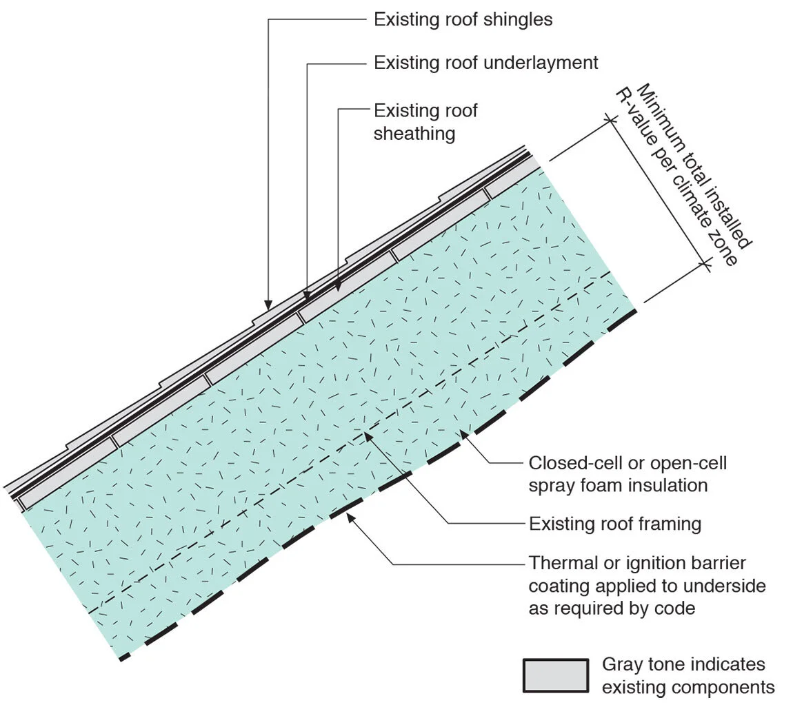
Unvented attic approach 1
2) rigid insulation and a nail base installed above the sheathing and under the roof covering (shingles, metal roofing, etc.) with additional fibrous insulation below the roof sheathing. This configuration also provides a ventilation space between the rigid insulation and the nailbase. This approach can provide better thermal performance and better resistance to ice dams than a conventional vented attic approach.

Unvented attic approach 2, showing a vented roof
Vented Roof Requirements:
Ventilation shall be provided at a ratio of 1 square foot of free vent area for each 150 square feet of attic floor—with vents placed proportionately at the eaves (e.g., soffits) and at or near the ridge.
Vented roofs shall have continuous vent openings at eaves and at the ridge.
Where permitted by the roof configuration, a ventilation channel at least 2” deep shall be maintained clear from eave to ridge at each roof framing bay.
Where a skylight, dormer or other obstruction precludes a continuous eave-to-ridge ventilation channel, provision shall be made for venting framing cavities above and below the obstruction.
In hipped roof or valley configurations, ventilation openings shall be provided to achieve similar ridge and eave ventilation opening area.
Wind blocking shall be installed at the perimeter of the attic to prevent roof ventilation from moving through or under the insulation. The wind blocking must be a solid material that is sealed to the wall top plate and to roof rafters. The blocking should extend to within 2” of the roof sheathing and seal to a vent baffle. See details below.
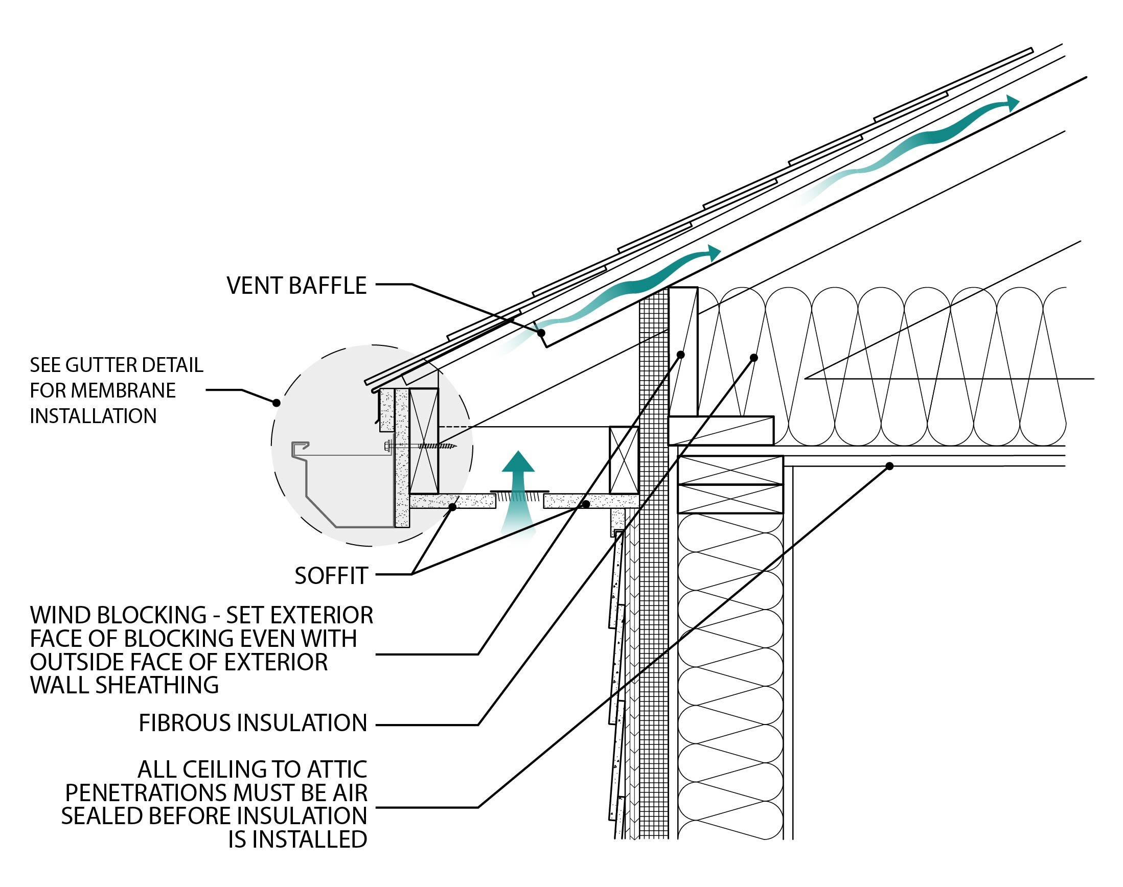
A vent baffle shall be installed to extend along the roof slope to a point 12” above the top of the attic insulation.

Unvented Roof Requirements:
The roof shall be designed and constructed with an airtight connection from the roof air barrier to the wall air barrier.
The unvented roof shall meet the provisions of IRC 806.5 regardless of whether the IRC is applicable to the building.
GUTTER AND RAIN LEADER INSTALLATION:
For Re-Roofing of Existing Buildings
Remove existing gutters carefully if they are to be reused.
Remove any/all screw fasteners at the roof edge.
For New Buildings and Re-Roofing of Existing Buildings
Gutters, existing and new will be installed with the appropriate hangers and spacing to effectively secure them to the building. Hangers should be no greater than 2 feet apart. Include hanger type in specifications.
Place a self-sealing bituminous membrane or the equivalent between the gutter and the fascia at location of gutter fasteners. See image of roof detail at gutter below.
If fascia board is visible above the top edge of the gutter, install a flashing tucked under the roof edge membrane or drip edge and lapping into the gutter.
Downspouts/rain leader will be installed effectively to collect and transport water to grade and away from building. Connect gutter to underground storm water system or to sloped lateral piping that opens on a sloped finish grade a minimum of 5 ft from the foundation or into a rainwater management system.
Using of splash-blocks is not permitted for new construction. If existing, ensure the slope of the splash blocks is away from the building as part of the preventative maintenance plan.
The downspouts/rain leaders should be 4” Schedule 40 PVC, painted to match the direct adjacent building color. Exterior Acrylic Paint specified for plastics should be used. Provide product information with bid.
Do not install gutter/leaf guard unless approved by POAH Communities Director of Maintenance. If approved, gutter guard should be installed without damaging existing roof or gutter.
Ensure gutters are installed with the correct slope to downspouts.
Install the gutter at an effective distance below the roof edge to allow rain water to enter and not back up into building.

PRODUCTS:
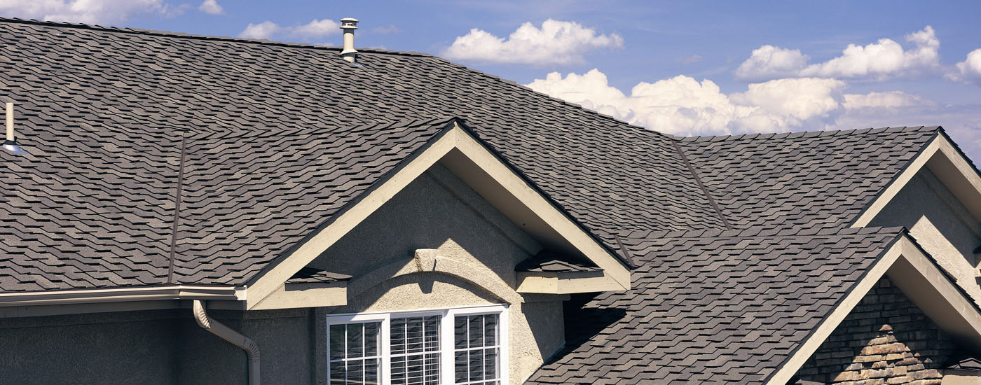
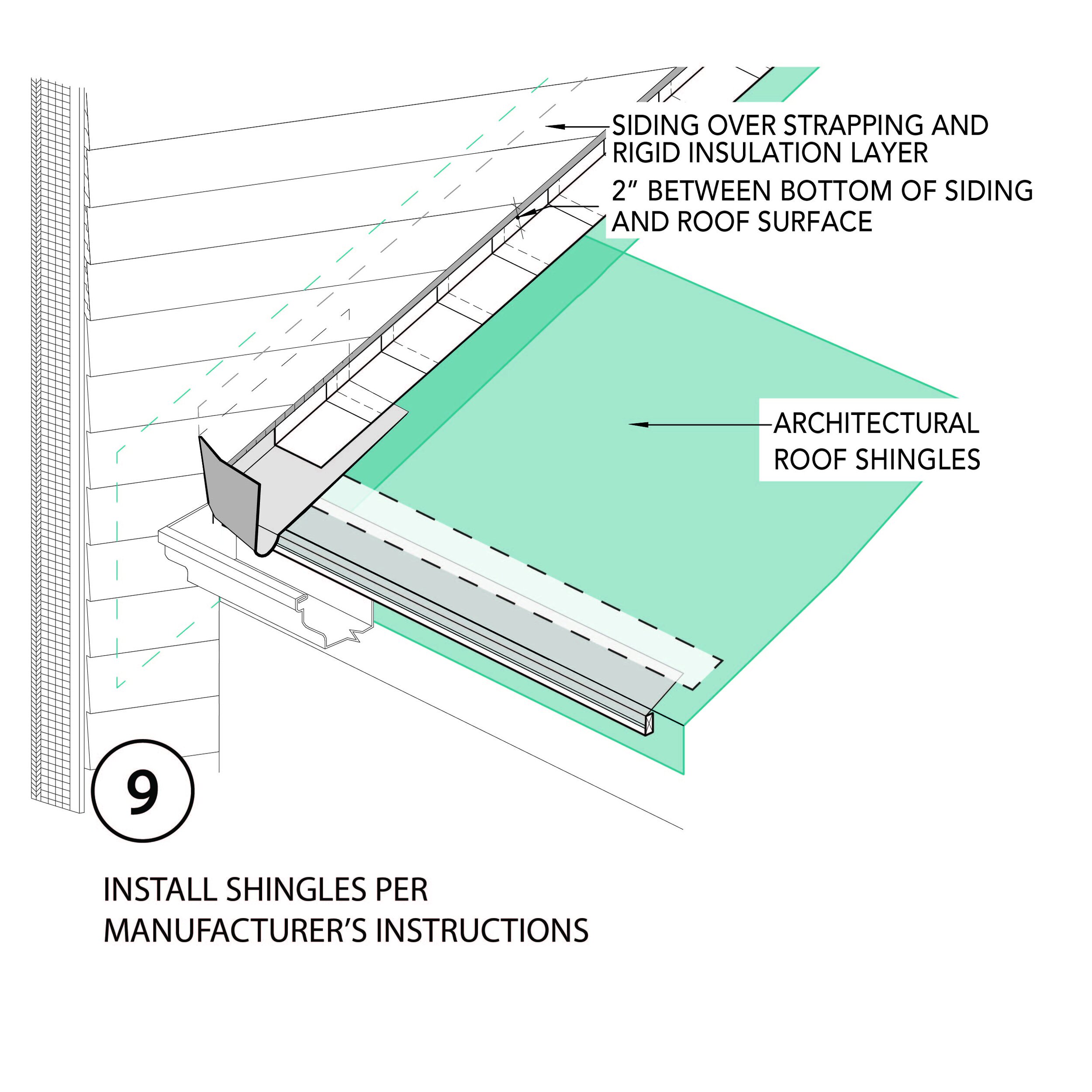
Architectural Shingles are preferred over 3-tab shingles for durability.
WARRANTY:
Labor Warranty: A separate 10-year labor warranty should be provided by the roofing installer. Most roofs that fail during the roof product warranty do so because they were installed incorrectly and in conflict with the manufacturer's recommended installation.
SPECIFICATIONS:
EPA Indoor airPLUS New Construction: Where code is not updated to include these specifications, refer to this document for more details.
High Wind Conditions: Seal the roof deck using one of the following three options, per the IBHS Fortified Hurricane and High Wind Standards:
1) Install a self-adhered (peel and stick) membrane over the entire roof deck (recommend a #15 felt bond break between membrane and shingles);
2) Install a nominal 4-inch-wide roof deck flashing tape over all roof sheathing panel seams and cover with #30 felt or equivalent synthetic underlayment.
VENTILATION & ICE DAMS
VENTILATION & ICE DAMS
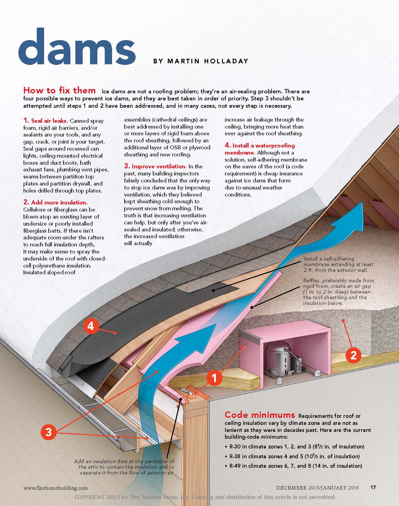
TECHNICAL BRIEF: ICE DAMS
Where ice dams do occur, it is important to understand the causes so that an effective solution can be implemented.
Ice dams are a symptom of poor thermal and air leakage control for roofs in cold winter climates. When diagnosing the causes of ice dams, it is critical to first determine if the roof system is a vented or an unvented roof (see Roof Configuration above). Never allow bath and kitchen exhaust to terminate in an attic. For more information on ice dams and how to avoid them, please view Fine Home Building's article referenced below.
Note: Ice dams should not occur in new buildings since following code provisions would control the mechanisms that cause ice dams. Incidents of ice damming in newer buildings may be reason to seek remedy from the designer, the contractor or both.