HEATING: EXISTING CONSTRUCTION
HEATING: EXISTING CONSTRUCTION
HEATING:
EXISTING CONSTRUCTION
This PDF was last updated on 04/09/2024. Please redownload if you’re currently working from an older version.
GENERAL INFORMATION
GENERAL INFORMATION
WHEN TO USE THIS BASIS OF DESIGN SECTION:
This BOD section should be used for 1) rehab projects to guide Architects, Engineers, and Development staff, and 2) during system replacement to guide maintenance staff. Modifications to existing heating equipment present significant and uncommon opportunities to improve performance, increase heating system efficiency and reduce utility costs.
REQUIREMENTS FOR ALL SYSTEMS
REQUIREMENTS FOR ALL SYSTEMS
REQUIREMENTS FOR ALL heating SYSTEM types during rehab:
When work to upgrade or replace the existing heating system is being considered, the following requirements should be reviewed by the project team:
1. EVALUATE CONVERSION TO HEAT PUMPS:
POAH’s preferred approach is to remove existing heating systems and to install new central heat pump systems with heat recovery (VRF-HR). For requirements on heat pumps, see the Heating + Cooling: New Construction section of the Basis of Design.
If converting to heat pumps is not possible, proceed with the following requirements, as well as those listed for specific system types (below):

Central VRF System
2. ALL NEW EQUIPMENT (HEAT PUMP OR NOT) MUST BE SIZED USING ACCA MANUAL J AND S, OR ANSI/ASHRAE/ACCA STANDARD 183:
New heating and cooling equipment shall be sized to meet calculated loads for the specific building or space served. Rule-of-thumb sizing is not acceptable. For buildings 3 stories or less in height use ACCA Manual J to calculate building loads and ACCA Manual S to size equipment. For buildings over 3 stories in height calculate heating and cooling loads according to ANSI/ASHRAE/ACCA Standard 183 and size equipment not greater than these loads.
When calculating heating and cooling loads use the following interior conditions:
Maximum of 74F for heating (this satisfies HUD’s requirement of 68F)
Minimum of 72F for cooling
3. PREDICTIVE MODELING FOR ENERGY CONSUMPTION AND COST:
POAH desires to have an estimate of energy consumption and cost for operation of the new building. Engineers shall provide estimates of energy use and cost for each of the following, broken out by common-meter energy use vs. resident-meter energy use:
Heating energy use for primary heating fuel
Heating electrical energy use (for fossil fuel systems, this would capture the electrical associated with pumps and fans)
Cooling energy use
DHW energy use for primary water heating fuel
DHW electrical energy use (as for heating, this would capture electrical use associated with pumps and burner/vent fans)
Ventilation energy use
Lighting
Plug loads
4. USE PROGRAMMABLE THERMOSTATS:
See the Thermostat section of the Basis of Design for more information.
Note: PTAC units will not include separate thermostats.
5. INCLUDE SPECIFICATIONS FOR COMMISSIONING (CX):
The following specification sections are required in all projects. Commissioning specifications to be reviewed, updated to reflect the current project, and included within the design specification. The HVAC Section (Division 23) must reference the following specifications:
Section 019013 – General Commissioning Specification
Section includes general and specific requirements that apply to the implementation of commissioning process for HVAC&R systems, assemblies, and equipment.Section 019013.01 Sample Commissioning (CX) Plan:
Provide a sample Cx Plan. This document outlines the organization, schedule, allocation of resources, and documentation requirements of the commissioning process. Each commissioning plan should include:Commissioning Objectives
Systems to be Cx.
Project team contact list, Cx roles and responsibilities of team, general management plan, communication protocols.
Summary of Cx process, schedule for Cx activities.
Documentational requirements. Plan for delivery and review of submittals, systems manuals, and other documents and reports.
Process and schedule for completing construction checklists and manufacturer's prestart and startup checklists for HVAC&R systems, assemblies, equipment, and components to be verified and tested.
Certifications: installation, prestart checks, and startup procedures have been completed. Ready for testing.
Verification of testing, adjusting, and balancing (TAB) reports.
Sample Issues Log and Corrective Action document.
Section 230800 - Commissioning of HVAC
Section includes commissioning process requirements for HVAC&R systems, assemblies, and equipment.If a Building Automation System (BAS/BME/EMS) is to be installed, the Integrated Automation Cx specifications within Section 23 HVAC will also require the following specification. All Cx specifications will also need to reference this specification:
Section 250800 - Commissioning of Integrated Automation
Section includes commissioning process requirements for BAS.
The Cx specifications within Section 23 HVAC must also reference the following specifications, as applicable to the project:
Section 220800 - Commissioning of Plumbing
Section includes commissioning process requirements for plumbing systems, assemblies, and equipment.Section 260800 - Commissioning of Electrical
Section includes commissioning process requirements for electrical systems, assemblies, and equipment.
REQUIREMENTS FOR SPECIFIC SYSTEMS
REQUIREMENTS FOR SPECIFIC SYSTEMS
REQUIREMENTS FOR specific heating system types during rehab:
1. CENTRAL BOILERS WITH HYDRONIC DISTRIBUTION:
Evaluate the possibility of converting the system to an air-source heat pump, VRF system. The electrical system should be evaluated for capacity to carry heat pumps. If the electrical system does not have capacity, consider upgrading the electrical system. If a VRF system is not feasible and a gas boiler is to remain, proceed with upgrade of the plant and distribution as follows:

Central Boilers with Hydronic Distribution
1. Determine Water Quality:
When replacing boilers, determined if the boiler failed prior to its expected service life. Collect data on any previous water quality tests and premature system failures. Corrosion due to hard-water, chemical imbalances, oxygen in the system are typical culprits. A water treatment conditioning device may need to be installed within the boiler plant to minimize future corrosion. Water strainers need to be inspected for debris and materials within the system. On all existing systems, at the design exploration phase, perform a test of water hardness and chemistry. Check all pump strainers for debris and indications of distribution deterioration.
2. Determine if system includes galvanized piping:
Galvanized piping over time corrodes from the inside, reducing flow rates through the piping and causing costly leaks inside concealed walls and floors. If galvanized pipes are found, the project team must evaluate replacing the entire piping system (this applies to both the heating and plumbing system).

Galvanized piping
3. Inspect pipes embedded in concrete.
Leaks will degrade concrete, in turn the concrete will increase the speed of metal pipe corrosion.
4. Boiler Plant:
1. Boiler: use modulating condensing boilers
2. Boiler Controls: use Outdoor Air Temperature (OAT) Reset that modulates based on change in outdoor temperature (ΔT). The OAT sensor for the OAT reset controller must be:

Modulating condensing boiler

Outdoor Air Temperature (OAT) Reset
1. located on the exterior face of the building.
2. located on the North side of the building; I.E. it should not be affected by changing temperatures caused by the sun. Alternative shaded locations may be suitable, subject to POAHs approval, where direct sunlight does not reach within 3’ of the OAT sensor and the surface that it is mounted to does not fluctuate with sunlight.
3. OAT sensor must be away from any devices that may affect its temperature reading, such as dryer or bathroom exhausts vents or AC/heat pump compressors.
3. Piping Configuration: If replacing distribution piping, utilize primary-secondary configuration. Use tertiary if needed for wings or auxiliary loads.
4. Building Loop Pumps: use lead lag, VFD pumps.
5. Building Loop Pump controls: control by pressure, or pressure and ΔT
1. Pressure sensor 2/3 along building loop
2. ΔT between loop supply leaving boiler room and loop return entering boiler room
6. Pipe Insulation:
1. Pipes up to 1 ½” diameter: use minimum 1 ½” thick tubular insulation
2. Pipes greater than 1 ½” diameter: use minimum 2” thick tubular insulation.
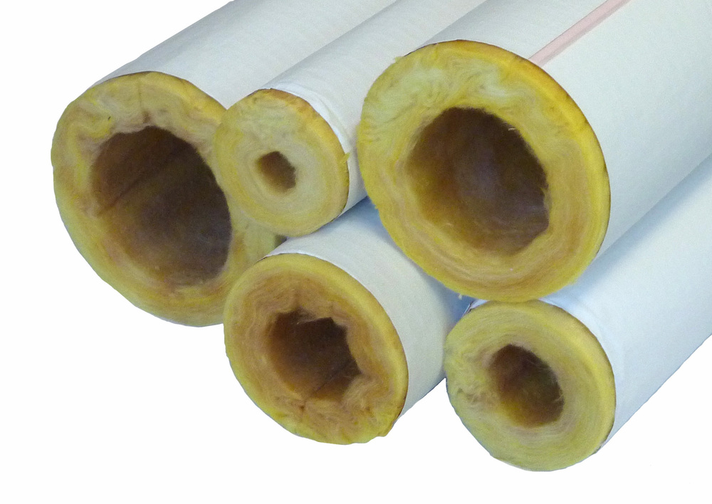
Pipe insulation
7. Combustion Exhaust Venting:
The exhaust vent must be located away from ventilation intakes, operable windows, etc. Refer to the International Mechanical Code (IMC) or the manufacturer’s installation instructions.
1. Inlet and outlet need to be located above anticipated snow load. Clearances above grade must account for not just average snowfall, but also snowdrifts and piles made from snow plowing/blowing.
2. Configure the exhaust vent such that condensate will not fall upon any building surfaces or walks.
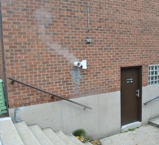
This boiler vent deposits condensate on the wall of the buildings and on the stairs leading to a shared laundry facility.
8. Demolish unused flue/vent and patch the vent penetrations:
When converting the hot water heating to either electric heat-pump or direct-vent combustion, there typically will be an existing exhaust vent that is no longer needed. Abandoned exhaust vents should be demolished and the ceilings, floors, roofs and/or walls that the vent went through should be patched and made good. The abandoned shaft must be closed and sealed at the floor of the attic.
1. Where the vent penetrated a roof and or wall, the water control of must be restored with the water control layer properly shingle lapped.
2. The ceiling of the boiler room must be patched and sealed.
3. Floor penetrations that are accessible or can be access as part of the renovation work should be sealed air tight and as required for fire safety.
4. If the vent cannot be fully demolished – e.g., the flue chase is in occupied apartments with no provision for work in those apartments – then the accessible portions of the vent should be demolished with the chase and vent sealed at the top and bottom.
5. If using the vent chase for new vent or intake pipes, or refrigerant lines, or ventilation ductwork, electrical service, etc. be sure to seal around the pipes and wires where they enter the chase. The top and bottom of the chase should be closed and sealed.
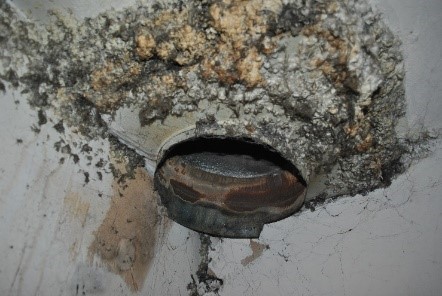
This abandoned exhaust vent provides a direct air leakage path to the exterior. It requires patching.
9. Heat Exchanger (HX): Evaluate history of HX seal replacement, dates and reasons for replacement; evaluate if the HX requires premature seal replacement. If HX requires disassembly and new seals, check water quality as previously discussed within this BOD section. Check condition of HX, are the chambers “plugged” with debris, scaling, or water hardness, indication (symptoms) of distribution system issues. Ensure strainers (filters) on both supply sides to the HX, in locations that are easily accessed by maintenance. If there is a debris or water quality issue, DO NOT replace HX or seals without addressing water issues.

Heat exchanger (HX)
5. Distribution using fintube/baseboard radiators:
1. Insulate accessible piping
2. Zone piping:
1. provide isolation valves for zone piping if not already present. Use ball valves, do not use gate valves. Gate valves typically wear faster and will require replacement, they are more prone to corroding in a position. They have a higher tendency to leak. Ball Valves last longer and are less prone to leaking.
2. provide a bypass if needed to allow for individual zone control
3. Radiators: when replacing radiators, replace with high-output radiators capably of meeting the space load with 120F water
4. Zone Valves: provide mechanical zone valves controlled by a zone thermostat
1. Low voltage zone valves for compatibility with thermostats and safety
5. Distribution using fan coils:
1. Change filters
2. Wherever possible and where not already present, provide zone valve and bypass so heating output can be controlled

Fintube/baseboard radiators
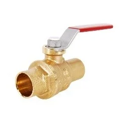
Ball Valves
Fan Coil
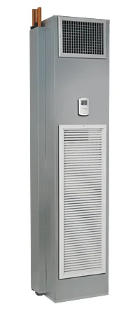
2. INDIVIDUAL APARTMENT FURNACE WITH DUCTED DISTRIBUTION:
Replacing a ducted furnace system may present an opportunity to convert to an air-source heat pump system. If the furnace is part of a split system with an outdoor compressor, the electrical system should be evaluated for capacity to carry heat pumps. If the electrical system does not have capacity, consider upgrading the electrical system. If an air-source heat pump system is not feasible and a gas furnace is to remain, proceed with the following:
1. Furnace: use condensing furnace with variable speed for higher efficiency
2. Blower motors: use ECM or variable speed
3. Ductwork insulation and sealing: Insulate and seal all accessible ductwork (Evaluate comprehensive duct sealing, e.g., Aeroseal)
4. Combustion Exhaust Venting: see Combustion Exhaust Venting Section listed above under “Central Boilers with Hydronic Distribution”.
5. Investigate adding cooling to existing system: If not already provided, provide an evaporator coil and exterior condenser to provide air-conditioning capability to the existing system.

Condensing Furnace with Variable Speed

ECM blower motor

Seal all accessible ductwork
3. PTAC SYSTEMS:
Investigate removing all PTAC units and installing new air-source heat pumps. If upgrading to air-source heat pumps is not feasible and PTAC units are to remain, consult with Building Design and Performance to determine the appropriate approach. The following measures apply to systems that will remain as PTAC:
1. PTAC types:
1. For Heat Pump PTAC units with electric resistance “back-up” heating: The controls for the PTAC unit must allow Heat Pump only heating down to a change-over temperature of no more than 40F.
2. EER rating of AC function must be 10 or higher
3. Thu-wall Sleeves:
1. The wall opening in which the PTAC sleeve is installed must be fully flashed and treated like a window opening (fully flashed, able to drain, continuously sealed at inside perimeter)
2. Cold climates: Line the wall opening with rigid foam insulation (min. compressive strength of 15 psi) to control condensation on the outside of the sleeve in the wall cavity.
3. Insulate and seal the perimeter of the wall sleeve to avoid drafts.
4. Multiple speed fans: use models with 2-speeds, or more.
5. Thermostats: do not use remote thermostats.
6. Transfer Ducts to adjoining rooms:
1. Duct connecting the PTAC unit with the distribution duct/plenum must be sealed to the PTAC unit discharge. Verify that supply air does not leak and is supplied at supply grilles only.
2. Provide a manual balancing damper in the ductwork.
3. Balance system supply air.
7. Ventilation through PTAC Units:
1. Warm, humid climates zones 1 and 2: Ventilation may be provided through the PTAC unit only if the PTAC unit provides dehumidification of the ventilation air. Dehumidification of ventilation supply air is also recommended for PTAC units in humid climate zones 3 and 4.
2. Mixed humid climates zones 3 and 4: Ventilation may be provided through the PTAC unit only if the PTAC unit provides either dehumidification of the ventilation air or ERV with a latent efficacy of at least 50%.
3. Cold climates, zones 5 and higher: Ventilation may be provided through the PTAC unit only if the PTAC unit provides energy recovery or heat recovery ventilation with a total recovery efficiency of not less than 65%.
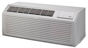
PTAC unit

PTAC thru-wall sleeve