VENTILATION
VENTILATION
VENTILATION
This PDF was last updated on 04/11/2024. Please redownload if you’re currently working from an older version.
GENERAL INFORMATION
GENERAL INFORMATION
WHEN TO USE THIS BASIS OF DESIGN SECTION:
This BOD section should be applied in all new construction and rehab projects. This section should also be referenced and applied during capital planning to guide the scope of upgrades to existing buildings.
VENTILATION TYPE:
Ventilation has significant impact on resident health, resident comfort and building energy use. The purpose of ventilation is to:
exhaust airborne contaminants,
dilute airborne contaminants that cannot be effectively removed, and
to provide fresh air.
There are three types of ventilation systems (in order of preference):
A. Balanced Exhaust and Supply with Recovery
B. Balanced Exhaust and Supply without Recovery
C. Exhaust Only
A. Balanced Exhaust and Supply with Recovery
B. Balanced Exhaust and Supply without Recovery

C. Exhaust Only Ventilation
REQUIREMENTS
REQUIREMENTS
Ventilation REQUIREMENTS
MEASURABLE DESIGN METRICS: Include in all designs
The following will be measured during and post construction:
PREDICTED ENERGY: During design, the mechanical engineer must provide projected energy consumption for any modification or new system. Energy consumption will be verified with actual energy data post construction.
DUCT TIGHTNESS: Existing ductwork to be sealed with Aeroseal or equivalent, perform pre and post sealing leakage tests. New ductwork shall not exceed the sum of 2.5 CFM50 per register per shaft, and 2.5 CFM50 per floor per shaft during testing. (Other certification or code requirements may have tighter requirements). Duct tightness will be measured during construction.
FLEX DUCT: Only used for transitions in lengths less than 6’.
FAN EFFICIENCY: Engineer to provide CFM/watt for each fan and the ventilation system in aggregate. Fan efficiency will be measured during building commissioning.
ERV EFFICIENCY: Engineer to provide sensible and latent efficiencies at designed airflow (CFM) for specified equipment for approval. System will be tested.
AIR CHANGES: Engineer to provide the calculated CFM required by space as well as for the building ventilation in aggregate (CFM/bedroom, CFM/sf). Air flow will be measured during building commissioning.
VENTILATION SYSTEM LEAKAGE CONTROL: For fans installed directly through wall or ceiling finishes (e.g., ceiling bath fan), the fan housing shall be sealed to the interior finish.

MOCKUP: A mock-up must be completed to measure sone (noise) level of new fans + existing ductwork.
PREFERRED STRATEGIES
PREFERRED STRATEGIES
APPROVED VENTILATION STRATEGIES
This section outlines the ventilation strategies approved by POAH. All ventilation system designs should be reviewed by the Design & Building Performance Dept. Any deviation from the Approved Ventilation Strategies require prior approval from the Design & Building Performance Dept.
APARTMENT SOURCE
APARTMENT SOURCE
Apartment OR IN-UNIT Ventilation
Exhaust (SOURCE CONTROL VENTILATION)
BATHROOM EXHAUST THROUGH (SHARED ERV OR HRV):
Every bathroom must include an exhaust fan that runs continuously. This approach employs continuous exhaust flow to achieve source control of excess humidity and odors. Ideally supply and exhaust systems are balanced and utilize recovery in the form of an ERV or an HRV.
At a minimum, the bath exhaust fans should:
Run continuously in each bathroom at a 25 CFM for background exhaust.
Bath Exhaust should never terminate into the attic.
Seal the shaft all ductwork or all vertical ductwork to 5cfm at 50 Pascals per floor or less
Install Constant Airflow Regulators (CARs) for each exhaust intake grille to control exhaust flow rate.
Coordinate with Background Ventilation design to create a balance.
KITCHEN EXHAUST (SHARED ERV OR HRV):
Kitchen exhaust is either intermittent through a capture hood over the cook-top or continuous through a general area exhaust located in the cooking area.
Continuous General Kitchen Exhaust: preferred method to integrate with Background Ventilation ERV. Every kitchen must include exhaust with a through wall/ceiling grill that:
Runs continuously at a 35 CFM for background exhaust.
Ensure exhaust grill is a minimum 6’ distance from cook-top.
Ensure washable filter at the exhaust grill.
Review design with ERV manufacturer.
Install recirculation capture hood over cooking range.
Install Constant Airflow Regulators (CARs) for each exhaust intake grille to control exhaust flow rate.
Coordinate with Background Ventilation design.
Range Hood: If continuous general kitchen exhaust through ERV is not possible, every kitchen must exhaust to exterior by using one of the following systems:
Range hood with integral fan exhausted directly to exterior; or
Range hood connected to a shared exhaust riser served by a rooftop fan exhausted to exterior.
The following applies to all range hood installations:
Sone level should be maximum 7.
Kitchen exhaust fan ductwork should never terminate into attic space.
Kitchen exhaust fan should include back draft damper.
CFM rating should be minimum 150.
Assist capacity required for buildings 3 stories and above. Install direct drive exhaust riser fan with variable speed barometric control to maintain duct pressure after existing ductwork has been sealed.
Range hood should be deep enough that Range Queen, when installed, is not visible. Range Queen Product information is found within the Rangehood BOD section. See link below.
Sample products are located in the RANGEHOOD page of the APPLIANCES section:
SUPPLY (FRESH AIR):
BALANCED VENTILATION SYSTEM WITH RECOVERY PREFERRED SYSTEM IN NEW CONSTRUCTION AND REHABS:
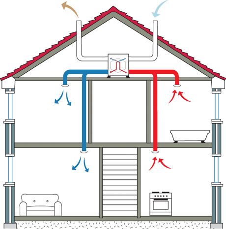
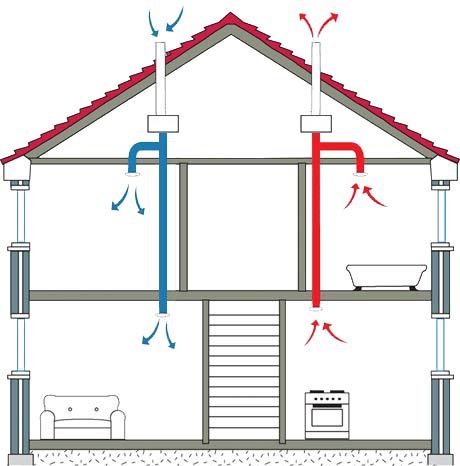
Balanced ventilation can be described as exhausting stale/humid air and suppling fresh air at equal rates (cfm). The best design is general exhaust from the kitchen and bathroom and supply to the living room and bedrooms. Ideally provide balanced ventilation with Energy Recovery Ventilation (ERV) units. Heat Recovery Ventilation (HRV) may be permitted in dry climates, but requires prior approval from the Design & Building Performance Dept. Using a recovery system saves energy by capturing heat and humidity in the exhaust air. The captured heat is used to temper the supply air. There are a few strategies for installing a balanced ventilation system with recovery, see below for descriptions.
SEMI-CENTRALIZED ERV (OR HRV)
This is a horizontal ventilation approach that eliminates the need for vertical duct risers, associated fire dampers. It can be used in midrise and high-rise buildings with a double loaded corridor.
ERVs located on each floor. May require/be advantageous to have more than one ERV per floor.
Horizontal supply and return air ducts from units to ERV(s).
Supply air is ducted to each living room and each bedroom.
Supply air duct is insulated for condensation control.
Exhaust air from bathrooms and general area kitchen exhaust.
Rangehood kitchen exhaust risers should NOT be connected to the ERV/ HRV due to grease buildup.
Insulated horizontal outdoor air and exhaust air duct from ERV(s) through exterior wall.
Minimize unconditioned air duct length, locate close to an exterior wall.
Install Constant Airflow Regulators (CARs) for each supply and exhaust location.
Locate ERVs in serviceable locations:
Ceiling mounted ERVs require ceiling access for filter changes, but do not require mechanical rooms. Can be installed in the corridors.
Floor mounted ERVs require mechanical rooms.
Provide post ERV refrigerant coil or hydronic coil
Provide enthalpy control (control humidity/moisture) of supply air. Every ERV requires humidity (moisture) control of post-ERV air.
Control Discharge Air Temperature (DAT) (Supply air)(variable) for comfort based on season. E.G. 55F DAT in summer and 70F DAT in winter.
ERV must have economizer. Controls must be capable of incorporating economizer when OA is beneficial.
Architectural coordination requirements:
Provide adequate floor-to-floor height for coordinating ducts with other services.
Accommodate supply and exhaust penetrations through enclosure.
SEMI-CENTRALIZED ERV OPTIONS:
Examples of successful ERVs – Ventacity Ceiling Mount Ventilators:
VS250CMe 60-270 CFM
VS400Cme 120-400 CFM
VS900Cme 200-900 CFM
VS1200Cme 300-1200 CFM
https://www.ventacity.com/products/ventilation-family/
CENTRAL ERV (OR HRV)
A more traditional approach which locates the ERV in a central location with vertical and horizontal duct distribution. This approach allows for minimizing the number of penetrations through the exterior enclosure but will require more penetrations through assemblies within the building.
ERV(s) are located:
Internally, such as in the attic or mechanical room.
Preferred for ventilation system performance and ERV durability.
Provide adequate access for future replacement of ERV. I.E., does not require cutting open a roof to replace ERV.
Rooftop.
Minimize rooftop ductwork.
Supply air is ducted to each living room and each bedroom.
Supply air duct is insulated for condensation control.
Exhaust air from bathrooms and general area kitchen exhaust.
Rangehood kitchen exhaust risers should NOT be connected to the ERV/ HRV due to grease buildup.
If ERV(s) is internal, insulate horizontal outdoor air and exhaust air duct from ERV(s).
Horizontal and/or vertical supply and return air ducts from units to ERV(s).
Install Constant Airflow Regulators (CARs) for each supply and exhaust location.
ERV should control supply air:
Provide enthalpy control (control humidity/moisture) of Discharge Air (supply air). Every ERV requires humidity (moisture) control of post-ERV air.
Control Discharge Air Temperature (DAT) (Supply air)(variable) for comfort based on season. E.G. 55F DAT in summer and 70F DAT in winter.
ERV to temper the air with:
Provide post ERV refrigerant coil or hydronic coil.
Integral heat pump for large ERV.
ERV must have economizer. Controls must be capable of incorporating economizer when OA is beneficial.
CENTRALIZED ERV OPTIONS:
Examples of successful ERVs – Ventacity Ceiling Mount Ventilators:
VS1000Rte 75-1000 CFM
VS3000Rte 750-3000 CFM
INDIVIDUAL APARTMENT ERV (OR HRV)
Individual apartment ERVs (or HRVs) are suitable for single dwellings and townhomes where a larger ducted system is not practical. It offers the advantage of apartment-level control, off-the-shelf products and minimized risk of cross-contamination between apartments.
ERV is located within the unit:
Insulated horizontal outdoor air and exhaust air duct from ERV(s) through exterior wall.
Minimize unconditioned air duct length, locate close to an exterior wall.
ERV supply:
Supply air is ducted to each living room and each bedroom.
Alternatively supply air is ducted to the return of the Fan Coil Unit (FCU); FCU is used for post ERV tempering. This requires further design consideration:
FCU diffusers must not cause drafts, comfort issues.
Control strategy to ensure air is circulated to occupied spaces when FCU thermal setpoint is met.
Supply air duct is insulated for condensation control.
Exhaust air from bathrooms and general area kitchen exhaust.
Rangehood kitchen exhaust risers should NOT be connected to the ERV/ HRV due to grease buildup.
Requires periodic in-unit equipment maintenance.
INDIVIDUAL ERV OPTION:
Examples of successful ERVs: Panasonic FV-10VE2
https://na.panasonic.com/us/home-and-building-solutions/ventilation-indoor-air-quality/energy-recovery-ventilators/intelli-balancetm-100-balanced-air-50-100cfmHeat pump ventilators
These systems can provide:
Ventilation
HEPA filtration
Dehumidification
Heat-Pump for tempering the air.
Similar mechanical design considerations as ERV, but larger ducts for higher CFM.
Architectural considerations: require a closet.
COMMON SOURCE
COMMON SOURCE
Common Area EXHAUST (Source Control Ventilation)
The following strategies apply to:
Trash rooms.
Janitor closets.
Common area kitchens
Elevator machine rooms (check local building codes for requirements)
Other areas outside of apartments where airborne contaminants are generated.
Rooms to be evaluated for airborne contaminants by design team and source control ventilation to be based on the presence of contaminants:
No harmful contaminants:
Shared exhaust system through ERV
Run continuously in each bathroom at appropriate CFM.
Seal the shaft to 5cfm at 50 Pascals per floor or less.
Install Constant Airflow Regulators (CARs) for each exhaust intake grille to control exhaust flow rate.
Coordinate with Background Ventilation design.
Potential harmful contaminants:
Exhaust to the exterior of the building:
Install Constant Airflow Regulators (CARs) for each exhaust intake grille to control exhaust flow rate.
Install direct drive exhaust riser fan with variable speed barometric control to maintain duct pressure within parameters for CAR operation.
COMMON AREA SUPPLY (FRESH AIR)
BALANCED VENTILATION WITH RECOVERY REQUIRED:
Background ventilation is part of the same system as in unit Semi-Centralized ERV or Centralized ERV. Similar strategy will be used.
Calculate the required ventilation for the common areas, provide balanced ventilation for the space.
Provide additional supply air to spaces that have adjacent rooms with exhaust. For example, if a trash room with exhaust is accessed from a corridor, provide the makeup air to the corridor to balance the system.
Corridors shall not be used as supply air plenum for apartments. All unit entrance doors need to be weather-stripped to maintain unit compartmentalization.
EXISTING CONDITIONS
EXISTING CONDITIONS
existing Exhaust and SUPPLY sYSTEM IMPROVEMENTS:
Utilize existing exhaust to incorporate an ERV to precondition supply air.
Modifications
Modify exhaust system(s) to incorporate ERV(s)
Combine unit bathroom exhausts in attic space or at roof.
If general area kitchen exhausts are used,
Ensure 6’ from cooktop with washable filter and combine unit kitchen exhausts in attic space or at roof.
Install Constant Airflow Regulators (CARs) for each exhaust location.
Replace existing supply air system (AHU/MAU/DOAS) with ERV using the exhaust to pre-condition.
Locate in attic or on roof. More significant rehab projects can utilize the horizontal semi-central approach.
If ERV is located in attic, for future replacement:
Ensure it can be brought in through existing openings to attic.
Or retrofit new adequately sized access.
Do not rely on cutting open building enclosure for future replacements.
ERV to temper the air with:
Provide enthalpy control (control humidity/moisture) of Discharge Air (supply air). Every ERV requires humidity (moisture) control of post-ERV air.
Control Discharge Air Temperature DAT (supply air) (variable) for comfort based on season for comfort. E.G. 55F DAT in summer and 70F DAT in winter.
ERV must have economizer. Controls must be capable of incorporating economizer when OA is beneficial.
Supply air to the building:
Preferred approach: supply air ducts to common spaces, and unit living rooms, and bedrooms.
Requires in-unit retrofit of supply duct.
One option is to utilize soffits to conceal the supply duct.
If supply air ducts cannot be retrofitted to each unit at the time of the rehab, ensure that the common area duct can incorporate future upgrades to achieve in unit balanced ventilation.
Supply air duct is insulated for condensation control.
COMPARTMENTALIZATION
Refer the Basis of Design Building Enclosure section for all Compartmentalization requirements.
Any opening or hole made from the installation of ductwork, equipment, pipework, refrigerant lines, electrical, controls, other MEP, or any penetrations caused by the ventilation system installation and modification discovered during retrofit shall be air sealed.
LAST AND LEAST FAVORABLE OPTION:
Prior approval of POAH’s Design & Building Performance Dept. is required for the following option to be used. This assumes there is no feasible way for a project to install balanced supply and exhaust through ERVs.
Supply pre-conditioned, filtered outdoor air to the corridors as makeup air to the in-unit exhausts. Air supplied to corridors will not effectively supply outdoor air to units. Requires unit entry doors to be undercut, most fire codes don't allow this, also eliminating unit compartmentalization goals.
The steps below are suggested for situations where direct ducted supply air to units or individual HRV/ERV are not possible.
EXHAUST ONLY SYSTEM IMPROVEMENTS:
SEAL DUCTS (VERTICAL AND HORIZONTAL)
Aero seal (or equivalent) all existing ducts
BATHROOM EXHAUST
Exhaust fan requirements include:
Run continuously at 25 CFM for background exhaust and be capable of boosting to higher CFM when activated by occupancy sensor
The boost capability shall include a "delay-off" operation whereby the fan continues to operate for an additional ~15 minutes after the boost is turned off.
The low-speed setting (variable) is typically set within the fan.
To provide separate background and boost capabilities, either:
There must be two wires to the fan, a constant power wire and control wire.
Fan must be type that has built in occupancy sensor for boost control.
If a fan replacement with the existing fan only having one wire (on/off) and fan does not have occupancy sensor:
Include re-wiring of fan in scope of work.
The separate boost capability may be achieved through specialized wall switch or controller at the switch box. Example: Tamarack SmartExhaust Bath Fan Control. Contact POAH Design + Building Performance for other options.
Fans should be low noise.
Sone (measurement of sound) should be 0.9 maximum.
Ductwork cannot be loose, or uninsulated.
A mock-up must be completed to measure sone level of new fans + existing ductwork.

Airtightness and Measurements:
Seal Ducts (vertical and horizontal) Aero seal (or equivalent) all existing ducts.
Use mastic or tape to seal any gaps between the ductwork and/or fan housing before installing fan or grill.
Seal between duct-boot and sheetrock.
After installation, the fan should be measured to confirm appropriate draw.
Bathroom exhaust fan options:

Panasonic
WhisperGreen Select
CFM: 30 - 110
Sone: 0.3 - 0.8
CFM/Watt: 11.5 - 15.1
Manufacturer Number:
FV-05-11VKS1

Panasonic
WhisperSense Motion Sensor
CFM: 80
Sone: 0.3
CFM/Watt: 5.1
Manufacturer Number:
FV-08VQC5
BATHROOM EXHAUST FAN ON ROOF
Exhaust requirements include:
Run continuously in each bathroom at a 25 CFM for background exhaust.
Install Constant Airflow Regulators (CARs) for each exhaust intake grille to control exhaust flow rate.
If variable CFM exhaust is needed for boost, use Aldes Zone Register Terminals with CAR dampers.
Install rooftop direct drive exhaust riser fan with variable speed barometric pressure control to maintain duct pressure.
Seal the shaft with Aeroseal to 5cfm at 50 Pascals per floor or less
KITCHEN EXHAUST
Continuous General Kitchen Exhaust: assumes ERV cannot be retrofitted at this time. Every kitchen must exhaust to exterior by a through wall/ceiling grill to rooftop exhaust system (existing buildings).
Run continuously at a 35 CFM for background exhaust.
Ensure washable filter at the exhaust grill.
Install Constant Airflow Regulators (CARs) for each exhaust intake grille to control exhaust flow rate.
Install rooftop direct drive exhaust riser fan with variable speed barometric pressure control to maintain duct pressure.
Coordinate with Background Ventilation design for ERV/AHU.
Range Hood with Intermittent Kitchen Exhaust: This requires fan powered range hoods. Every kitchen must exhaust to exterior by using one of the following systems:
Range hood with integral fan exhausted directly to exterior; or
Range hood connected to a shared exhaust riser served by a rooftop fan exhausted to exterior.
The following applies to all range hood installations:
Sone sound should be maximum 7.
Kitchen exhaust fan ductwork should never terminate into attic space.
Kitchen exhaust fan should include back draft damper.
CFM rating should be minimum 150.
Assist capacity required for buildings 3 stories and above. Install rooftop direct drive exhaust riser fan with variable speed barometric pressure control to maintain duct pressure.
Range hood should be deep enough that Range Queen, when installed, is not visible. Range Queen Product information is found within the Rangehood BOD section. See link below.
Coordinate with Background Ventilation design.
The intermittent exhaust will yield a lower 24/7 average exhaust rate.
Engineer to use diversity factor to calculate continuous makeup supply air.
COMPARTMENTALIZATION
Compartmentalize between units and between unit and corridors.
Any opening or hole made/discovered during retrofit shall be air sealed.